
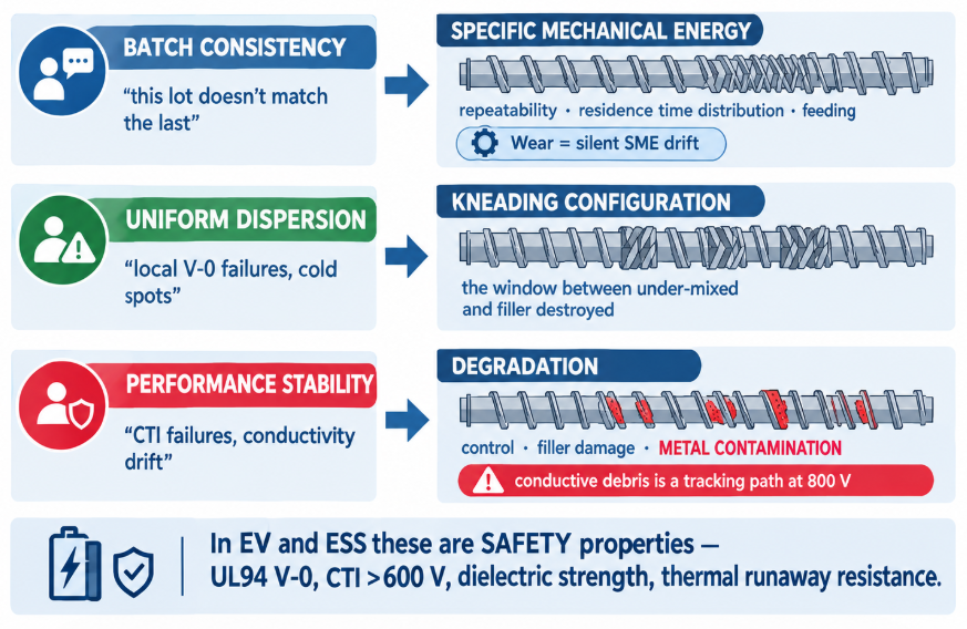
Compounders supplying the EV and energy-storage supply chain are held to three things by their customers — batch-to-batch consistency, uniform dispersion, and stable performance — and all three are decided inside the twin-screw extruder by the element configuration, the process energy it delivers, and the wear state of the screws and barrel. What makes this market different from ordinary compounding is what those properties are: UL94 V-0 flame retardancy, comparative tracking index above 600 V for 800 V platforms, dielectric strength, thermal conductivity, and thermal-runaway barrier performance. A dispersion defect here isn’t a cosmetic reject — it’s a flammability test failure or a tracking path in a busbar insulator. This guide maps each downstream requirement to the screw-side variable that controls it, covers the compound families and what each asks of the hardware, and explains why wear is the hidden variable behind all three.
By the BLOOM Engineering Team
What the Downstream Actually Requires
| Requirement | Typical specification | Where it’s used |
|---|---|---|
| Flame retardancy | UL94 V-0 at 1.5 mm; thin-wall grades V-0 at 0.75–0.8 mm; halogen-free (non-brominated, non-chlorinated) | Module and pack housings, cell holders, covers |
| Thermal runaway resistance | Withstand 1,200°C flame for 10 minutes with reverse-side temperature below ~210°C; a single cell can exceed 800°C within 30 seconds | Pack enclosures, cell-to-cell barriers |
| Tracking resistance | CTI > 600 V as platforms move from 400 V to 800 V+ | Connector housings, busbar holders, charge-port components |
| Dielectric strength | Tens of kV/mm class, with safety factor | Busbar insulation, cell terminal insulation |
| Thermal conductivity | Filled grades from ~1 W/m·K (insulating) upward; electrically insulating or conductive variants | Module thermal management, heat-spreading housings |
| Chemical resistance | Li-ion electrolyte resistance | Cell holders, terminal insulation |
| Mechanical | Stiffness, impact, creep, low CTE — often 30% glass fiber, or long-glass-fiber | Structural pack components, trays |
Two structural trends raise the bar further. Cell-to-pack architectures remove modules but push higher stiffness, flame retardancy, and dielectric requirements onto the remaining structural parts and busbar insulators. And the 800 V transition drastically elevates the risk of electrical tracking and arc faults — which is why CTI requirements climbed and why a conductive contaminant in an insulating compound became a safety issue rather than a quality note.
Requirement 1: Batch-to-Batch Consistency
The customer’s complaint is simple: “this lot doesn’t match the last one” — MFI drifted, colour shifted, mechanicals or flame test results moved. On the compounding line, that variation traces to whether the extruder delivered the same process history to every batch. Three screw-side variables control it:
- Specific mechanical energy (SME). The energy the screw puts into each kilogram of compound — a function of screw speed, throughput, and configuration — sets the dispersion state, the degradation level, and the fiber length. If SME drifts, everything downstream drifts with it. Wear is the silent SME drift: as clearance opens, the same screw speed delivers less effective shear, so a process that was in specification at commissioning slowly leaves it while every setpoint reads unchanged.
- Residence time distribution (RTD). A narrow RTD means every particle sees a similar history; a broad one means part of the batch is over-worked while part is under-mixed. RTD is set by configuration and fill — and again widened by wear as leakage over the flights increases.
- Feeding consistency. Filler and additive feeders that surge produce local concentration variation the screw must then even out — and if it can’t, the variation ends up in the pellet.
The practical consequence for compounders: log the SME. A rising or falling energy trend at constant throughput and speed is the earliest available warning of wear, long before output falls. Check the mechanical side against our wear limit calculator when the trend starts.
Requirement 2: Uniform Dispersion
Flame retardant that isn’t uniformly dispersed leaves local zones that fail the vertical burn. Thermally conductive filler that isn’t uniformly distributed leaves cold spots and a lower average conductivity. Glass fiber bundles that weren’t opened leave weak points. In every case the property the customer buys is a network property — it only exists if the additive is everywhere.
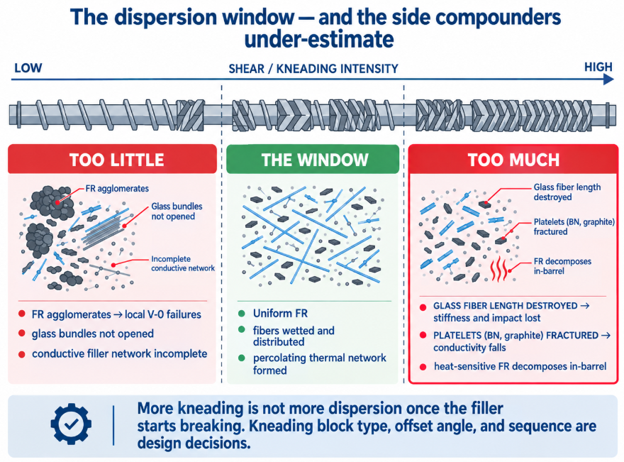
Dispersion is the kneading configuration’s job, and it has a window:
| Too little shear | The window | Too much shear | |
|---|---|---|---|
| Flame retardant (mineral, 50–65%) | Agglomerates → local V-0 failures | Uniform; fire performance consistent | Heat-sensitive FR (e.g., ATH) decomposes in-barrel |
| Glass fiber (30%+) | Bundles not opened; poor mechanicals | Fibers wetted and distributed | Fiber length destroyed → stiffness and impact lost |
| Thermally conductive fillers (60–80%) | Filler network incomplete; low conductivity | Percolating network formed | Platelet fillers (BN, graphite) fractured; conductivity falls |
| Pigments, additives | Streaks, specks | Homogeneous | Excess heat; degradation |
That right-hand column is the one compounders under-estimate. More kneading is not more dispersion once the filler starts breaking: glass fiber loses the length that gives the compound its stiffness, and platelet fillers lose the aspect ratio that gives them conductivity. The configuration has to land in the window — which is why kneading block type, offset angle, and sequence are design decisions, covered in our twin-screw elements guide and mixing section selection guide. The same dispersion-versus-damage trade-off governs LSZH cable compounds and dry battery electrodes; EV structural compounds simply add fiber length to the list of things shear can destroy.
Requirement 3: Performance Stability
Consistency is about matching the last batch; stability is about the property surviving the process at all. Three mechanisms erode it:
- Thermal and shear degradation. Every kilojoule of excess SME is a kilojoule of degradation — molecular weight loss, colour, and for halogen-free FR packages, premature decomposition of the very additive that provides the flame rating.
- Filler and fiber damage. Covered above: the compound’s mechanical and thermal properties are carried by the filler’s geometry, and geometry can be destroyed.
- Metal contamination — the one that matters most at 800 V. Screw and barrel wear debris is metallic and conductive. In a filled compound running at 60–80% abrasive loading, it is being generated continuously — and in an insulating compound destined for a busbar holder or connector housing, a conductive particle is a potential tracking path. The property that failed wasn’t in the formulation; it was in the wear part. This is the same contamination logic that governs battery separator and dry electrode lines, arriving in the compounding step.
The specification consequence: wear surfaces must resist abrasion without shedding, which is a metallurgy and process-quality question — tungsten-carbide-bearing or nickel-alloy grades depending on whether the threat is pure abrasion or abrasion plus corrosion (halogen-free FR packages can release acidic by-products; see our nickel base alloy page).
The Compound Families
| Compound | Typical formulation | What the screw must do | Hardware implication |
|---|---|---|---|
| FR glass-fiber PP / PA housings | 30% GF + halogen-free FR package | Open fiber bundles and distribute FR without breaking fibers or decomposing FR | Abrasion from GF and mineral FR — wear-resistant elements and barrel; see glass fiber wear |
| Long-glass-fiber PP (trays, structural) | LGF pultrusion or long-fiber compounding | Maximize fiber length retention — gentle conveying, minimal kneading | Low-shear configuration; wear still significant |
| CTI >600 V connector grades (PA, PBT, PC blends) | Halogen-free FR, sometimes GF | Uniform FR dispersion; zero conductive contamination | Non-shedding surfaces; high polish |
| Thermally conductive (insulating) | 60–80% ceramic filler (alumina, BN) | Build filler network without fracturing platelets | Extreme abrasion — carbide-class construction |
| Thermally conductive (conductive) / EMI | Graphite, carbon fiber, metal fillers | Dispersion for percolation | Abrasive; contamination less critical but wear high |
| High-temperature busbar / terminal insulation (PPS, PEI, LCP) | Often GF-filled | Melt at 300–400°C class without degradation | Heat-stable metallurgy; see PEEK-class specification |
| Thermal-runaway barriers (ceramifiable, mica-filled) | Very high mineral loading | Distribute without decomposing | Abrasive; low-shear |
The pattern across the table: almost every EV/ESS compound is heavily filled, and many carry a heat-sensitive additive that must be dispersed without being cooked. That is the hardest twin-screw brief there is — and it is the one where wear does the most damage, because worn elements add uncontrolled shear exactly where the process needs control.
Wear: The Variable Behind All Three
It’s worth stating plainly because it unifies this guide. On an EV/ESS compounding line, wear:
- Drifts SME → batch inconsistency (Requirement 1)
- Widens RTD and adds uncontrolled shear → dispersion window missed, fillers damaged (Requirement 2)
- Sheds conductive debris → contamination in insulating compounds (Requirement 3)
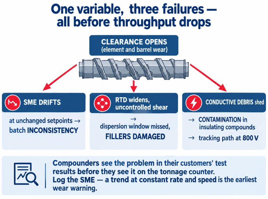
And it does all three before it reduces throughput — which is why compounders in this market see the problem in their customers’ test results before they see it on the tonnage counter. A wear-monitoring routine (SME logging, periodic element measurement, pellet metal-content checks) is not maintenance overhead here; it’s part of the quality system the customer is auditing. Our acceptance inspection checklist covers what documentation replacement elements should arrive with, and pelletizing problems that start at the screw covers the downstream consistency signature.
Symptoms and What They Point To
| Symptom | Likely cause |
|---|---|
| MFI, colour, or mechanicals drifting lot to lot with unchanged recipe | SME drift — wear, or feeding instability |
| Local V-0 failures on an otherwise passing compound | FR agglomeration — dispersion configuration, or feeder surging |
| Stiffness or impact below spec on GF compounds | Fiber length destroyed — configuration too aggressive |
| Thermal conductivity below expectation at correct loading | Filler network incomplete, or platelets fractured |
| CTI or dielectric failures with correct formulation | Conductive contamination — wear debris; check element and barrel condition |
| Discolouration, odour, FR performance loss | Thermal/shear degradation — excess SME, hot spots, residence |
| Rising energy consumption at constant rate | Wear — or fouled barrel cooling |
| Customer complaints rising over months with no formulation change | Wear — measure elements and bore before reformulating |
The three things an EV or energy-storage customer demands of a compounder — consistency, dispersion, and stability — are three views of one variable: whether the twin-screw extruder delivered the intended mechanical energy, in the intended distribution, without adding anything of its own, batch after batch; and the element configuration decides the first two while the wear state decides whether they hold.
At BLOOM, we manufacture twin-screw elements, barrels, and screws for compounding lines serving EV and energy-storage supply chains — wear-resistant, non-shedding element grades matched to filled and flame-retardant formulations, built to your configuration or reverse-measured from worn sets, with full material and dimensional documentation. If your customers are reporting lot-to-lot variation, or your FR, CTI, or conductivity results have started drifting with no formulation change, send our engineering team your compound and filler loading, extruder model and configuration, SME trend, and the symptom on WhatsApp and we’ll tell you whether it’s configuration, wear, or process. For the wider picture, see our compounding and masterbatch guide and types of twin screw extruders.
References and Further Reading
- Glass-Fiber PP EV Battery Pack Could Debut in 2024 and New PP Compounds Target Complex EV Battery Pack Applications, PlasticsToday — 30% glass-fiber-filled FR PP housings, long-glass-fiber FR PP trays, non-brominated/non-chlorinated FR meeting UL94 V-0 at 1.5 mm, and thermal-runaway testing at 1,200°C for 10 minutes with reverse-side temperature held below 210°C: https://www.plasticstoday.com/automotive-mobility/new-pp-compounds-target-complex-ev-battery-pack-applications
- Flame Retardant Polyamide Compounds for EV Powertrains and Batteries Market Outlook to 2035, IndexBox — the 400 V to 800 V+ transition drastically elevating electrical tracking and arc-fault risk, CTI > 600 V requirements for connectors and busbar holders, and cell-to-pack architectures raising requirements on remaining structural parts: https://www.indexbox.io/blog/flame-retardant-polyamide-compounds-for-ev-powertrains-and-batteries-market-to-2035-driven-by-stringent-safety-regulations-for-battery-packs/
- Materials for High Voltage EV Components in Batteries, Powertrain and EE, Covestro — CTI 600 V flame-retardant PC blends for cell holders and busbar carriers, and electrically insulating versus conductive thermally conductive compound grades: https://solutions.covestro.com/en/highlights/articles/stories/2022/electrifying-the-future-with-new-cti-fr-1-polycarbonates


Pingback: Thermally Conductive Compounds: Gentler Mixing Wins