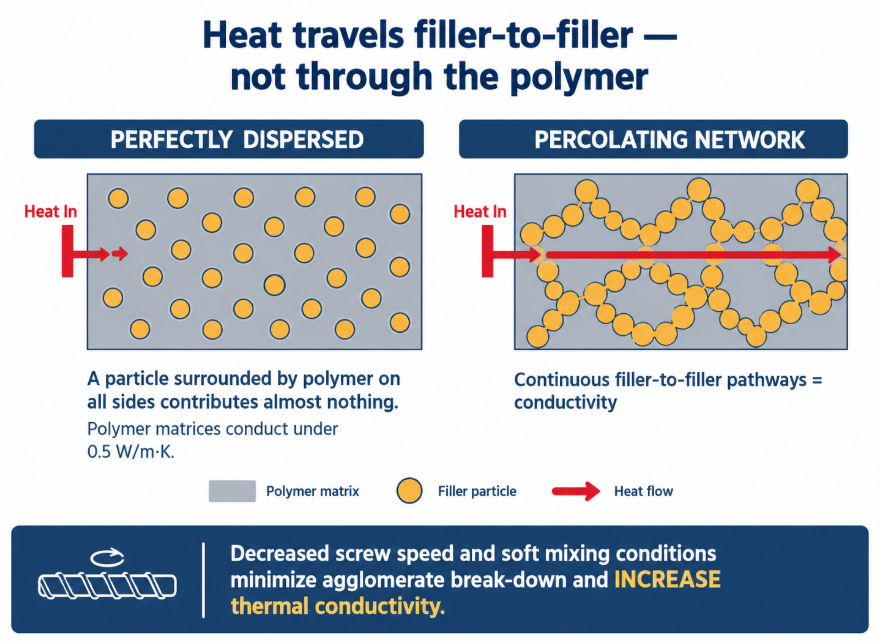
Thermally conductive compounding breaks the rule the rest of compounding runs on. Everywhere else, better dispersion means better product. Here, the property you are selling is a percolating filler network — heat travels through filler-to-filler contact, not through the polymer — so the filler agglomerates and platelet geometry that dispersion normally destroys are the thing that carries the performance. The filler supplier’s own guidance says it directly: decreased screw speed and soft mixing conditions minimize break-down of the agglomerate and increase thermal conductivity. At the same time, some shear is genuinely useful, because it exfoliates platelets into thinner flakes with more contact area. Landing between those two is the entire craft of this compound family — and doing it through a barrel carrying 60–80% hard ceramic is what it asks of the hardware.
By the BLOOM Engineering Team
Why the Usual Rule Inverts
In a flame-retardant or pigment compound, the additive works wherever it happens to be, so the goal is uniform distribution and the smallest practical agglomerate. Thermal conductivity doesn’t work that way:
- Polymer matrices conduct heat poorly — typically well under 0.5 W/m·K. The filler does essentially all the work.
- Heat must travel filler-to-filler. A perfectly dispersed particle surrounded by polymer on all sides contributes almost nothing; it needs neighbours it touches.
- So conductivity appears at a percolation threshold, when enough contacts exist to form continuous pathways through the part.
That is why thermal conductivity rises steeply with loading and why formulators push to 60–80% filler by weight — and why breaking up the structures that form contacts costs performance. Related, but distinct: electrical percolation. Insulating fillers such as h-BN and AlN have electrical resistivity above 10¹³ Ω·cm, so they can build a thermal network without building a conductive one — the property that makes them essential for EV busbar carriers and cell holders, where the compound must move heat and block current at the same time.
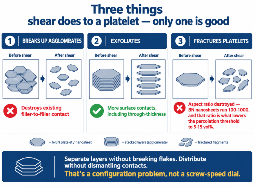
Three Things Shear Does to a Platelet Filler — Only One Is Good
| What shear does | Effect on thermal conductivity | Verdict |
|---|---|---|
| Breaks up agglomerates | Destroys existing filler-to-filler contact structures | ❌ Reduces conductivity — the documented reason soft mixing works better |
| Exfoliates platelets (separating layers along the basal plane into thinner flakes) | Creates more surface contacts, including through-thickness | ✅ Beneficial — documented as contributing to through-plane conductivity in h-BN composites |
| Fractures platelets (breaking them across the plane) | Destroys aspect ratio — BN nanosheets run 100–1000 aspect ratio, AlN whiskers 20–50, and that ratio is what lowers the percolation threshold to 5–15 vol% | ❌ Raises the loading you need for the same conductivity |
This is a far narrower window than “disperse it well.” The screw has to separate layers without breaking flakes, and distribute without dismantling contacts — which is a configuration problem, not a screw-speed problem you can dial in during a run.
Practically it points the same direction as the filler supplier’s advice: fewer and gentler kneading blocks, distributive rather than dispersive character, lower screw speed, and adequate length to distribute without working the material hard. The element-level logic is in our twin-screw elements guide and mixing section selection guide.
Filler Shape Changes the Strategy
| Filler | Shape | Intrinsic conductivity | Compounding character |
|---|---|---|---|
| Alumina (Al₂O₃) | Spherical/isotropic | ~20–30 W/m·K | Low aspect ratio hinders the conduction path, so high loading is needed; Mohs 9 — extremely abrasive |
| Hexagonal boron nitride (h-BN) | Platelet, anisotropic | 200–400 W/m·K in-plane, plus electrically insulating | Gold standard for insulating thermal compounds; soft itself, but fragile geometry |
| Graphite | Platelet, anisotropic | High | Conductive both ways — thermal and electrical |
| AlN | Whisker/particle | High, insulating | Aspect ratio 20–50; moisture-sensitive grades |
| Multimodal blends | Mixed | — | Large particles (10–100 µm) for primary pathways, small (0.1–1 µm) to bridge gaps, nano to improve interfacial conductance — reduces percolation threshold 30–50% versus single-size |
Two consequences for the screw.
Multimodal blends complicate feeding and mixing, not just formulation. Three particle populations must each end up where they belong — the large ones intact and in contact, the small ones filling gaps rather than sitting in clumps. That is distributive work, done gently, with feeder accuracy that holds the ratio.
Surface-treated fillers change what mixing is for. Silane coupling agents and similar treatments improve conductivity 40–60% at the same loading by improving the polymer–filler interface — but the treatment has to survive compounding and wet properly. Excess shear heat degrades coupling agents; gentle, thorough distribution helps them work.
Anisotropy: The Screw Sets Up What the Mould Finishes
Platelet fillers orient. In injection moulding, shear aligns BN flakes along the flow direction, which produces strongly anisotropic parts — one published PVDF/BN system measured 1.26 W/m·K in-plane against only 0.40 W/m·K through-plane at the same loading, while low-shear compression moulding of the same compound gave isotropic ~0.41 W/m·K both ways.
The compounder doesn’t control the moulder’s gate — but does control whether intact, high-aspect-ratio platelets arrive to be oriented at all. A compound whose flakes were fractured in the extruder cannot deliver in-plane performance downstream no matter how the part is moulded. In practice this is why two compounds at identical loading and identical formulation can test differently at the customer: the difference was made in the kneading section.
The Wear Problem: Mohs 9 at 70% Loading
Thermally conductive compounds are among the most abrasive duties in plastics:
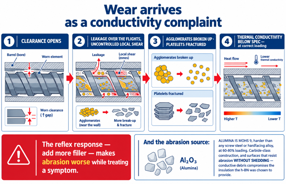
- Alumina is Mohs 9 — second only to diamond among common minerals, and harder than any screw steel or hardfacing alloy.
- Loadings of 60–80% mean the great majority of what passes the flight tips is ceramic. As with LSZH cable compounds, quantity compounds the hardness problem — except here the hardness is genuinely extreme too.
- Continuous production. These are volume automotive and electronics compounds, run in long campaigns.
That combination puts thermally conductive compounding squarely in tungsten carbide territory — carbide-bearing element grades and carbide-reinforced bimetallic barrel liners, not nitrided construction, and not standard hardfacing on high-alumina recipes. The reasoning is the same as on glass-fiber duty, one hardness step more severe.
And there is a second reason beyond service life. Wear debris is metallic and conductive. In an electrically insulating thermal compound destined for a busbar carrier or cell holder, conductive contamination compromises the exact property the h-BN was chosen to provide — the contamination logic that also governs battery separator and dry electrode lines. Wear surfaces here must resist abrasion without shedding, which is a metallurgy and application-quality question, not just a hardness number.
Why Wear Shows Up as a Conductivity Complaint
Worn elements and an opened bore change the process in exactly the direction this compound cannot tolerate:
Clearance opens
  → leakage over the flights, uncontrolled local shear
     → agglomerates broken up and platelets fractured
        → filler network degraded, aspect ratio lost
           → THERMAL CONDUCTIVITY BELOW SPEC at correct loading
So a line that has slowly started missing its conductivity target with no formulation change is describing wear, not chemistry — and the reflex response (add more filler) makes abrasion worse while treating a symptom. Measure first; check against our wear limit calculator.
Symptoms and What They Point To
| Symptom | Likely cause |
|---|---|
| Conductivity below spec at correct loading | Filler network degraded — over-shear, broken agglomerates, fractured platelets |
| Conductivity fell after a configuration or speed change | Too much kneading intensity — try fewer/gentler elements and lower screw speed |
| In-plane performance lost, through-plane unchanged | Platelet aspect ratio destroyed in compounding |
| Conductivity varies lot to lot | SME drift or feeder ratio error on multimodal blends — see our EV and energy storage compounding guide |
| Electrical insulation or CTI failures | Conductive contamination — wear debris, or a conductive filler cross-contamination |
| Surface defects, poor part finish | High loading plus incomplete wetting; coupling agent degraded by shear heat |
| Elements worn out far faster than on other compounds | Normal for high-alumina duty on under-specified metallurgy — upgrade rather than replace like-for-like |
| Melt temperature above setpoints | Viscous heating from high loading; check whether shear is also damaging filler |
Thermally conductive compounds are the case where the screw’s virtue is restraint: the network that carries the heat is a structure, not a state of uniformity, so the configuration that makes the best product is the one that distributes the filler while touching it as little as possible — through a barrel full of ceramic that is wearing the machine out while it does.
At BLOOM, we build twin-screw elements, barrels, and screws for thermally conductive compounding — carbide-class wear grades for high-alumina and mixed-ceramic loadings, non-shedding surfaces for electrically insulating grades, and configurations built for gentle distribution rather than aggressive dispersion. If your conductivity has drifted below target with no formulation change, or your elements are wearing out faster than the production plan allows, send our engineering team your filler system and loading, extruder model and configuration, screw speed, and conductivity trend on WhatsApp and we’ll tell you whether it’s configuration or wear.
References and Further Reading
- Boron Nitride Cooling Fillers Case Studies, 3M — thermal conductivity influenced during twin-screw compounding, with decreased screw speed and soft mixing conditions minimizing agglomerate break-down and increasing thermal conductivity; anisotropic platelet fillers versus low-aspect-ratio isotropic fillers, and multi-geometry filler combinations improving percolation: https://www.3mindia.in/3M/en_IN/design-and-specialty-materials-in/boron-nitride/case-studies/
- Design of Highly Thermally Conductive Hexagonal Boron Nitride-Reinforced PEEK Composites, ACS Applied Polymer Materials — 60 wt% h-BN in PEEK reaching 12.45 W/mK in-plane and 2.34 W/mK through-plane, with shear-driven exfoliation during compounding contributing through-thickness surface contacts: https://pubs.acs.org/doi/10.1021/acsapm.2c01534
- Thermally Conductive Polymer Composites for Power Electronics, PatSnap — h-BN in-plane conductivity of 200–400 W/m·K with resistivity above 10¹³ Ω·cm, BN nanosheet aspect ratios of 100–1000 and AlN whiskers 20–50 reducing the thermal percolation threshold to 5–15 vol%, multimodal filler distributions reducing the threshold 30–50%, and silane surface functionalization improving conductivity 40–60% at equal loading: https://www.patsnap.com/resources/blog/articles/thermally-conductive-polymer-composites-for-power-electronics/