
Extruder screw design is the engineering of a screw’s geometry — its zones, channel depths, length, pitch, and mixing features — to melt, mix, and pump a specific plastic correctly. Get the design right and the screw delivers stable output, complete melting, and good melt quality; get it wrong and you face surging, degradation, unmelted material, or premature wear. A screw isn’t a generic part — it is purpose-built for the material and process it runs. This guide walks through the fundamentals of screw design: the three-zone structure, the key geometric parameters, the main screw types, materials and surface treatment, and how the design changes for different plastics. Each section links to a deeper guide on that specific topic.
By the BLOOM Engineering Team
Understanding the Basics of Screw Design video
The Three-Zone Structure: The Foundation of Screw Design
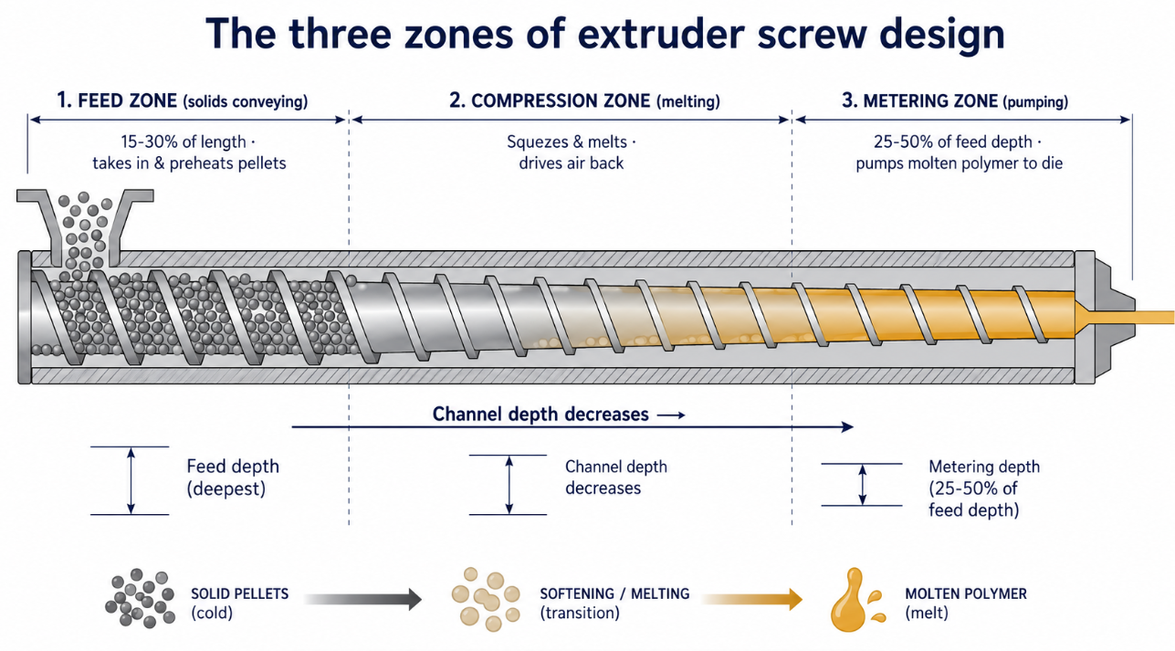
Almost every conventional single-screw design is built on three sequential zones, created by a constant pitch but changing channel depth along the screw:
- Feed zone (solids conveying). Constant, deep channels that take in solid pellets from the hopper and convey them forward. This zone preheats the pellets and is typically 15–30% of screw length. Channel depth here is set by the bulk density of the material.
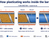
- Compression/transition zone (melting). The channel depth gradually decreases, squeezing the material as it melts. This compression drives trapped air back toward the hopper, compensates for the volume reduction as pellets become dense melt, and generates shear heat that melts the polymer. This is where the “barrier” sits on a barrier screw.
- Metering zone (pumping). Constant, shallow channels — typically 25–50% of the feed depth — that pump the now-molten polymer forward at a steady rate and pressure to the die. Mixing elements often live here.
One important exception to the three-zone logic: on a machine with a grooved feed barrel, compression happens in the barrel grooves rather than along the screw, so the feed section is cut very shallow and the compression ratio stays low. Our groove feed screw barrel guide covers how the screw geometry changes.
Here is how the three zones compare at a glance:
| Zone | Channel depth | Typical length | Job | Design driver |
|---|---|---|---|---|
| Feed | Deep, constant | 15–30% | Convey & preheat solid pellets | Bulk density of the material |
| Compression | Decreasing (tapered) | ~20–50% | Melt the polymer, drive out air | Compression ratio, material melting behavior |
| Metering | Shallow, constant (25–50% of feed) | 25–50% | Pump molten polymer at steady rate | Output rate, melt uniformity |
The reason this matters for design: each zone has a job, and the lengths and depths of the zones are tuned to the material. As industry veterans put it, these are the screw-design essentials that govern everything else (PlasticsToday: screw design essentials). The geometric zones don’t always match the functional zones — on a poorly-matched screw, solid material can survive well into the metering zone — which is exactly the kind of problem good design prevents. To understand how the whole machine works around the screw, see our how a plastic extruder works guide.
The Key Geometric Parameters
Screw design comes down to a handful of dimensions, and getting each one right for the material is the core of the craft.
L/D Ratio (Length-to-Diameter)
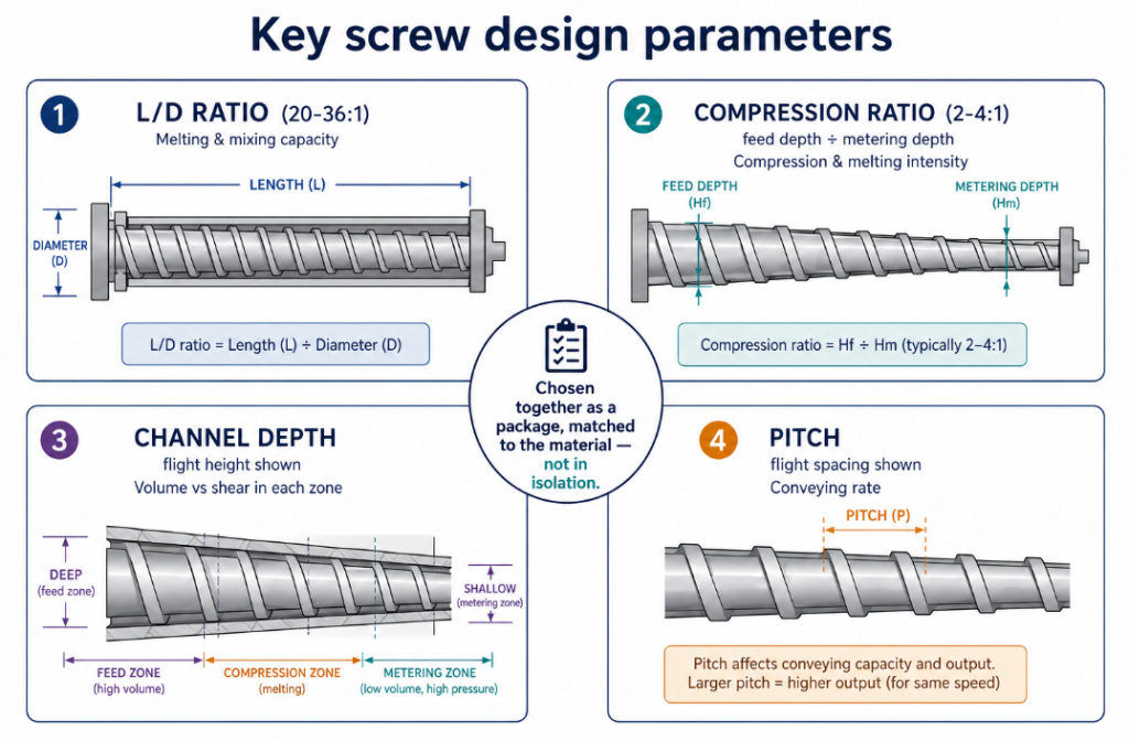
The L/D ratio — the flighted length divided by the screw diameter — sets how much room the screw has to melt and mix. Standard ranges run from about 20:1 to 36:1, with longer screws giving more melting and mixing capacity but also longer residence time. Longer is not automatically better: too high an L/D degrades heat-sensitive materials and can even limit output. For the full treatment, see our L/D ratio guide and, importantly, the downsides in are there disadvantages to a long extruder screw.
Compression Ratio
The compression ratio — feed channel depth divided by metering channel depth — determines how much the material is compressed as it melts, typically ranging from 2:1 to 4:1. Matching it to the material is critical: too high scorches heat-sensitive resins like PVC, too low leaves unmelted material. A mismatch causes premature wear, plugging, or burning. The full logic, plus recommended ratios by material, is in our compression ratio guide, and how to measure it on an existing screw in how to measure compression ratio.
Channel Depth and Pitch
Channel depth (flight height) controls volume and shear in each zone — deeper channels convey more but mix less; shallower channels mix and pump but generate more shear heat. Pitch (the axial distance per flight turn) is most commonly “square” (pitch equals diameter) but can be varied for specific effects. These two, together with diameter, define the compression ratio and the melting behavior. Low-bulk-density materials need deeper feed channels and higher compression ratios to account for the air they carry.
Putting the Parameters Together
The parameters aren’t chosen in isolation — they interact. A summary of how the main ones relate:
| Parameter | What it controls | Design trade-off |
|---|---|---|
| L/D ratio | Melting & mixing capacity, residence time | More melting vs more degradation risk |
| Compression ratio | Compression & melting intensity | Complete melting vs scorching sensitive resins |
| Channel depth | Volume vs shear in each zone | Throughput vs mixing & shear heat |
| Pitch | Conveying rate & residence | Output vs melting completeness |
This is why a screw must be designed as a package — see our introduction to extruder parameters for how these fit together.
Screw Types: Choosing the Right Architecture
Beyond the parameters, the overall screw architecture is a design decision driven by the material and process.
Here is how the main screw architectures compare:
| Screw type | Best for | Key strength | Typical applications |
|---|---|---|---|
| Single-screw, general-purpose | Steady extrusion of one material | Simple, high output | Pipe, profile, basic film |
| Single-screw, barrier + mixer | Materials needing melt uniformity | Complete melting, cooler melt | Blown film, demanding extrusion |
| Twin-screw, co-rotating | Compounding, mixing, filled materials | Intensive mixing, modular | Compounding, masterbatch, reactive |
| Twin-screw, conical | Rigid PVC profile | High torque at feed, gentle | Rigid PVC pipe & profile |
| Grooved-feed design | Slippery, hard materials | Strong solids conveying | HDPE pipe, high-output PE |
| Vented (two-stage) | Materials with volatiles/moisture | Devolatilization | Recycled, hygroscopic materials |
The right architecture follows from the material and the process — there’s no single best type.
Single vs Twin Screw
The first fork is single-screw versus twin-screw. Single-screw extruders are simpler and excel at high-output, steady extrusion of a single material (pipe, profile, film). Twin-screw extruders intermesh two screws for intensive mixing and are the choice for compounding, devolatilization, and heavily-filled materials. The full comparison is in our single screw vs twin screw guide.
Conical vs Parallel Twin Screw
Within twin-screw, the screws can be parallel or conical — a design choice affecting torque, shear, and the materials each suits (conical twin screws are common in rigid PVC profile). See conical vs parallel twin screw extruders.
Barrier Screws and Mixing Sections
A major design enhancement is the barrier screw — a secondary flight in the melting section that separates solid pellets from melt, forcing complete melting and a more uniform, cooler melt. Combined with a mixing section (Maddock, pineapple, or pin mixers) in the metering zone, this is the standard for film and any application demanding melt uniformity. Grooved-feed designs pair with specific screw geometries (shallower feed, deeper metering) for slippery, hard materials like HDPE, and vented (two-stage) designs add a decompression zone partway down the screw so volatiles can be drawn off under vacuum before the melt is recompressed and metered (PlasticsToday: the taming of the screw). The variety of screw types and their pros and cons is covered in our extruder screw types guide.
Twin-Screw Elements (Modular Design)
Twin-screw screws are built from modular elements — conveying elements, kneading blocks, mixing elements — assembled on a shaft. The arrangement of these elements is the design, tuned to where melting, mixing, and conveying should happen along the screw. See our twin-screw elements guide for how the elements work.
Materials and Surface Treatment: Design Beyond Geometry
A screw’s design isn’t only its shape — it’s also what it’s made of and how its surface is protected, because the screw has to survive the material it processes.
Base Material
The screw’s base steel must provide the torsional strength to turn without twisting and the foundation for surface hardening. Nitriding steel (38CrMoAlA) is the standard, but high-torque or long screws may need through-hardened tool steels or high-speed-steel cores for strength. See our guides on how to select screw materials and the 38CrMoAlA design guide, plus a head-to-head material comparison.
Surface Treatment
The flight surfaces and the bore wear against each other and against abrasive or corrosive material, so surface treatment is a core design decision: nitriding for general duty, hard chrome for corrosion, hardfacing (Colmonoy, Stellite) and tungsten carbide for abrasion, and bimetallic construction for the barrel. Matching the treatment to the threat — abrasion, corrosion, or both — is essential, and is covered fully in our coating and surface treatment guide.
Designing for the Material: One Size Does Not Fit All
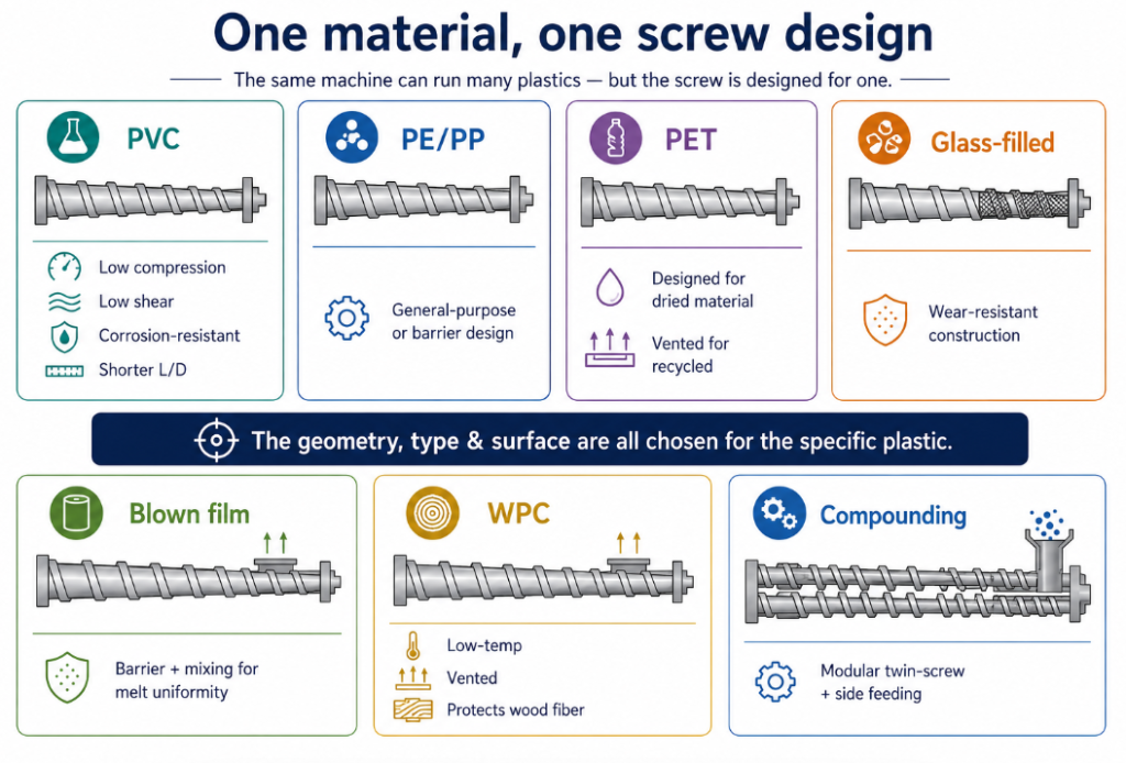
The unifying principle of screw design is that the geometry, type, and surface are all chosen for the specific plastic. The same diameter screw is designed very differently depending on what it runs:
- Heat-sensitive (PVC): lower compression ratio, lower shear, corrosion-resistant surface, shorter L/D — see our PVC screw and barrel guide.
- Polyolefins (PE/PP): general-purpose or barrier designs depending on output and melt-quality needs — see choosing a screw for PE and PP.
- PET: designed for a dried, hydrolysis-sensitive material, often vented for recycled streams — see our PET screw selection guide.
- Engineering plastics & glass-filled: wear-resistant construction for abrasive fillers — see our engineering plastics screw guide.
- Blown film: barrier-plus-mixing design for melt uniformity — see our blown film screw guide.
- WPC (wood-plastic): low-temperature, vented design that protects heat-sensitive wood fiber — see our WPC screw guide.
- Compounding: modular twin-screw element configurations with side feeding — see our compounding and masterbatch screw guide.
- Recycling: robust, often vented designs for contaminated, variable feedstock — see our recycled plastic screw guide.
This is why “what’s the best screw design?” has no universal answer — the best design is the one matched to your material, output, and machine.
Common Screw Design Mistakes
Knowing the parameters is one thing; the failures we are most often asked to fix come from a handful of recurring design mismatches:
- Wrong compression ratio for the material. The single most common one — running a polyolefin screw (3:1) on heat-sensitive PVC scorches it, while too low a ratio leaves unmelted material. The compression ratio has to match the resin, not be a default.
- Using a general-purpose screw for a demanding material. A “one screw for everything” approach under-performs on materials that need a barrier design (film), wear protection (glass-filled), or low shear (PVC). The generic screw runs, but poorly.
- L/D maximized instead of matched. Assuming a longer screw is always better, then degrading heat-sensitive material with excessive residence time, or even limiting output.
- Surface treatment that doesn’t match the threat. A nitrided screw on abrasive glass-filled compound wears out fast; a hardfaced screw on a corrosive resin still corrodes. The surface must match abrasion, corrosion, or both.
- Ignoring base-metal strength on long, high-torque screws. Specifying only surface hardness while the slender core lacks the torsional strength to resist twisting.
- A new screw in a worn barrel. Not a screw-design error exactly, but a system one — the clearance depends on both parts, so a perfectly-designed screw in a worn bore still leaks. Screw and barrel are designed and maintained as a pair.
Almost every one of these traces back to the same root: treating the screw as a generic commodity rather than a part designed for a specific material and process.
From Design to Manufacture
A complete screw design also has to be manufacturable and verifiable: the right steel, correct heat treatment, the specified surface hardness and depth, accurate geometry held to tolerance, and proper straightness. When ordering a custom or replacement screw, the design intent is communicated through a drawing or a sample screw plus the material and process details — see our custom screw RFQ guide for how to specify a screw correctly. For the broader picture of screws and barrels as a complete system — including selection and sourcing — see our complete guide to extruder screws and barrels.
Good extruder screw design is ultimately the discipline of matching geometry, architecture, material, and surface to a specific plastic and process — the three-zone structure tuned with the right L/D and compression ratio, the screw type and mixing features chosen for the melting and mixing the material needs, and the steel and surface treatment selected to survive the duty — so that the screw melts completely, pumps steadily, and lasts, which is exactly what a screw built for the job (rather than a generic part) delivers.
At BLOOM, we design and manufacture extruder screws and barrels engineered for your specific material and process — the right geometry, type, material, and surface treatment, built to drawing and verified. Whether you need a new screw designed from your material and output targets, or a replacement reverse-engineered from an existing screw, send our engineering team your details on WhatsApp and we’ll design the right screw for the job.


bokep anak sma
September 5, 2026 at 16:14Way cool! Some extremely valid points! I appreciate you writing this post and also the rest of the website is also really good.
Graham Bush
September 10, 2026 at 16:39Thanks for agreeing with our points! If you have a different take on anything, we’d love to hear that too.