Quick answer: measure the channel depth at the feed section and at the metering section, then divide the feed depth by the metering depth — that ratio is the compression ratio. Channel depth is the distance from the screw root (the shaft surface between the flights) to the top of the flight, which equals (barrel bore diameter − screw root diameter) ÷ 2. For a screw with a 12 mm feed channel depth and a 4 mm metering depth, the compression ratio is 3:1. Here is how to take the measurements correctly, and the pitfalls that throw the number off.
By the BLOOM Engineering Team
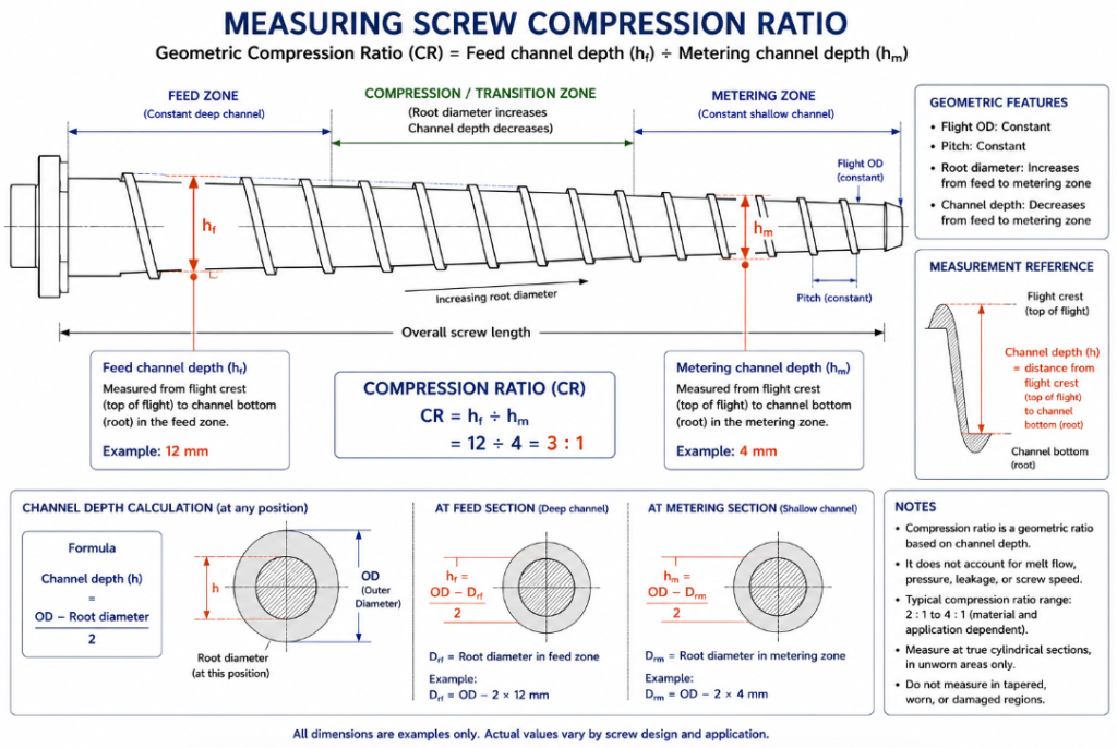
What You’re Actually Measuring
The compression ratio is the feed channel depth (hf) divided by the metering channel depth (hm) — hf/hm. Both are “channel depth,” also called flight height: the radial distance from the screw root surface to the top (outer edge) of the flight. Strictly, the compression ratio is the ratio of the volume of the first (feed) flight to the volume of the last (metering) flight, but for a standard constant-pitch screw it simplifies to the ratio of the channel depths, which is what almost everyone measures.
So the whole task comes down to measuring two depths accurately:
- Feed depth (hf) — the deep channel near the feed (hopper) end.
- Metering depth (hm) — the shallow channel near the discharge (die) end.
The compression ratio is simply hf ÷ hm.
Method 1: Direct Depth Measurement (Screw Removed)
The most reliable method, with the screw out of the barrel:
- Identify the zones. Find the feed section (deep, constant-depth channels near the shank/feed end) and the metering section (shallow, constant-depth channels near the discharge end). The transition between them has changing depth — don’t measure there.
- Measure the feed channel depth (hf). With a depth gauge or depth micrometer, measure from the screw root (the shaft surface at the bottom of the channel) straight out to the top of the flight, in the feed section. Take readings at a few points and average.
- Measure the metering channel depth (hm). Do the same in the metering section, near the discharge end.
- Divide. Compression ratio = hf ÷ hm.
Example: feed depth 12 mm, metering depth 4 mm → 12 ÷ 4 = 3:1.
A depth micrometer or a caliper depth rod sitting across the flight tops, dropped to the root, gives you the channel depth directly. Measure perpendicular to the screw axis, at the deepest point of the channel.
Method 2: From Diameters (Root and Outer)
If you can’t get a depth gauge into the channel, calculate depth from two diameters:
Channel depth = (screw outer diameter − screw root diameter) ÷ 2
- Measure the screw outer diameter (OD) — across the flight tips — with a micrometer or caliper. This is the same in feed and metering (the flights reach the same OD).
- Measure the root diameter at the feed section (the shaft diameter at the bottom of the channel) — this is smaller in the feed section (deep channel) and larger in the metering section (shallow channel).
- Compute each channel depth: (OD − root diameter) ÷ 2, once with the feed root diameter and once with the metering root diameter.
- Divide feed depth by metering depth.
This works because the flight OD is constant while the root diameter changes — a thinner root in the feed section means a deeper channel. Calipers across the root in each zone, plus the OD, give you everything.
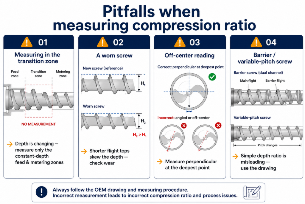
The Pitfalls That Throw Off Your Measurement
A few things commonly produce a wrong compression-ratio number — worth knowing before you trust the result:
| Pitfall | Effect | How to avoid |
|---|---|---|
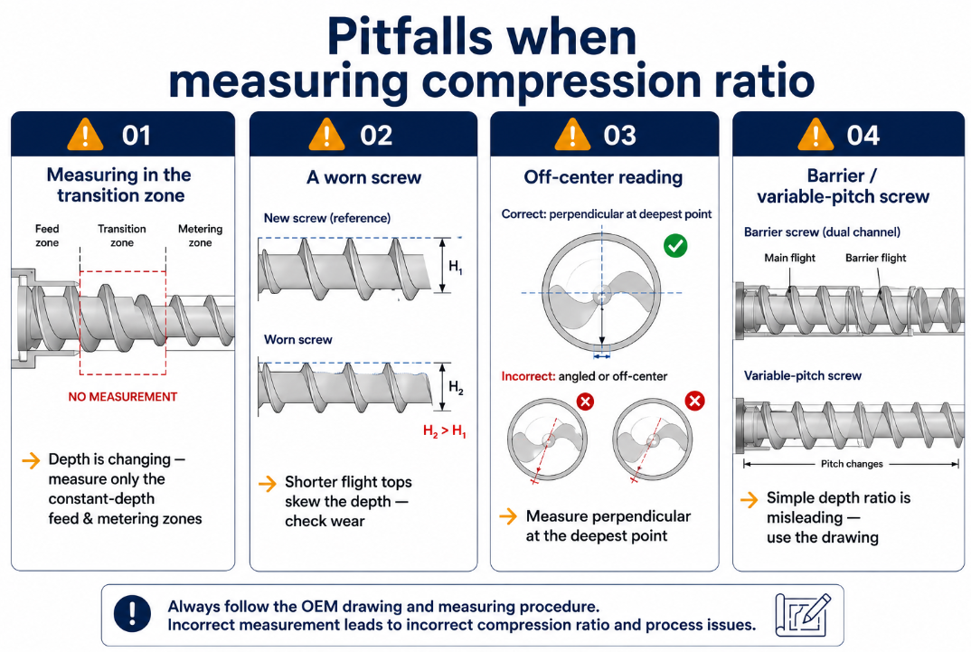
| Measuring in the transition zone | Depth is changing there → wrong number | Measure only in the constant-depth feed and metering zones |
| A worn screw | Worn flight tops are shorter → shallower apparent depth, skewed ratio | Note wear; compare to the original drawing if possible |
| Not measuring at the deepest point | Off-axis or off-center reading | Measure perpendicular to the axis at the channel’s deepest point |
| Variable-pitch or barrier screw | The simple depth ratio doesn’t capture the real compression | These need the drawing or maker’s spec, not a simple depth ratio |
That last one matters: on a barrier screw or a variable-pitch screw, the feed-to-metering depth ratio does not tell the whole story, because the geometry separates melting from metering. For those, the compression ratio as a simple depth ratio is misleading — see why in our compression ratio guide.
Also remember the wear point: if the screw is worn, the flight tops are reduced and your measured OD (and so the channel depth) is off. Measuring compression ratio is a good moment to also check wear — see how much screw wear is acceptable. And the screw has to be out to measure it properly, which means a safe removal — see how to remove an extruder screw from the barrel.
Why Measure It at All?
Knowing your existing screw’s compression ratio is useful in three situations:
- Diagnosing a processing problem. If you are scorching heat-sensitive material (too-high ratio) or getting unmelted particles (too-low ratio), measuring the ratio confirms whether the screw geometry is the culprit.
- Ordering a replacement or duplicate. If you want a screw that performs like your current one, the compression ratio (with the other dimensions) is part of the spec — though sending the old screw or its drawing is more accurate than measurements alone.
- Changing materials. If you are switching to a material that needs a different ratio, knowing what you have tells you whether your current screw will work or you need a new design.
In all three cases, the measured number is a guide. The most reliable path, especially for a replacement, is to give a screw maker the old screw (as a sample) or its OEM drawing, plus what you process — see our custom screw RFQ guide.
The Bottom Line
To measure an existing screw’s compression ratio: measure the channel depth in the feed section and in the metering section, and divide feed by metering. Channel depth is (OD − root diameter) ÷ 2, or a direct depth-gauge reading from root to flight top. Measure only in the constant-depth zones, watch for wear that skews the reading, and remember that barrier and variable-pitch screws aren’t captured by a simple depth ratio. The number tells you whether your screw’s compression matches your material — and is one input (alongside the old screw or its drawing) when ordering a replacement.
At BLOOM, we design and manufacture extruder screws to the right compression ratio for your material — and we can reverse-engineer a replacement from your existing screw or drawing. If you’ve measured your screw’s compression ratio and aren’t sure it suits your material, or you want a duplicate or improved screw, send our engineering team the measurements or the old screw details on WhatsApp and we’ll help. For what the number means, see our extruder screw compression ratio guide.