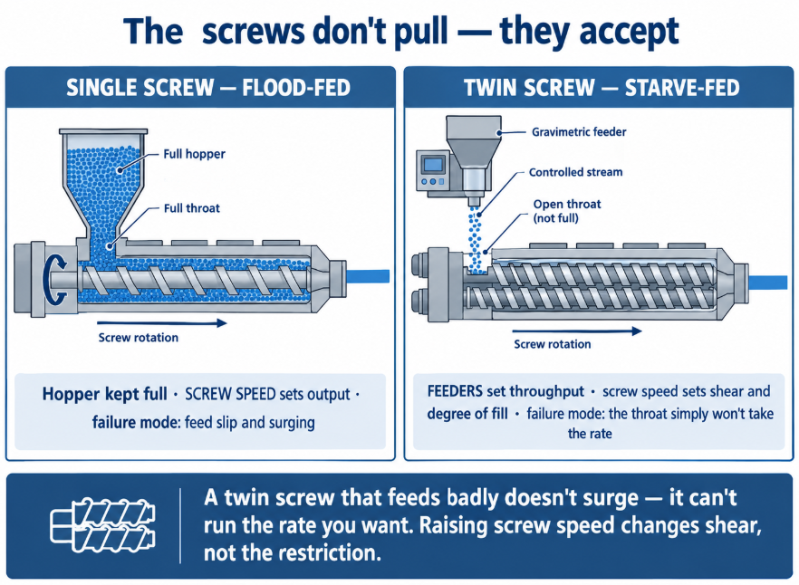
On a twin screw extruder, the feed barrel is where throughput is won or lost — and it is the section most often left as whatever the machine came with. Unlike a single screw, a twin screw is starve-fed: feeders meter material into the feed throat at a controlled rate, and the extruder processes exactly what it is given. The screws don’t pull material in; they accept it. Which means the feed barrel’s only job is to let the feeders deliver their rate without the material bridging, entraining air, softening, or refusing to go down — and when it can’t, no amount of screw speed downstream recovers the lost kilograms. This guide covers what the feed barrel does, how open and closed sections differ, why it must be cooled, and how barrel layout decisions are made.
By the BLOOM Engineering Team
Starve-Fed Changes Everything
| Single screw (flood-fed) | Twin screw (starve-fed) | |
|---|---|---|
| How material enters | Hopper is kept full; screw rotation pulls material in | Feeders meter material in at a steady, controlled rate |
| What sets throughput | Screw speed and the screw’s conveying capability | The feeders |
| What screw speed does | Sets output | Sets shear, mixing intensity, and degree of fill |
| Feed barrel’s role | Grip and convey against the barrel | Accept the delivered rate without obstruction |
| Failure mode | Feed slip, surging | Bridging, air backflow, rate limitation |
This distinction is the reason feed barrel problems look different on a twin screw. A single screw that feeds badly surges; a twin screw that feeds badly simply cannot take the rate you want to run — the feeder is calling for kilograms the throat won’t pass. Operators often respond by raising screw speed, which changes shear and specific mechanical energy but does nothing about the restriction. The types of twin screw extruders guide covers why intermeshing screws convey positively in the first place; the feed barrel is where that capability is either used or wasted.
Open and Closed Barrel Sections
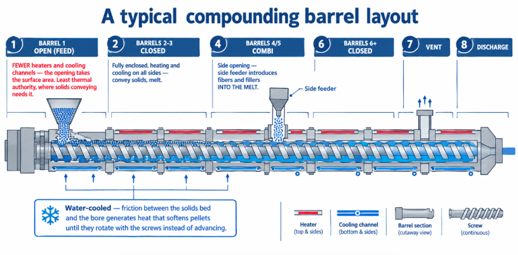
A twin screw process section is assembled from barrel segments, and they are not identical:
| Open (feed) barrel | Closed barrel | Combi barrel | |
|---|---|---|---|
| Structure | Has the feed opening cut through the top | Fully enclosed bore | Closed, with a side opening for a side feeder |
| Temperature control | Fewer heaters and cooling channels — the opening takes the space | Heating and cooling on all sides | Between the two |
| Usual position | Barrel 1 (sometimes Barrels 1 and 2) | Barrels 2 onward | Typically Barrel 4 or 5 |
| Purpose | Accept the feed, convey solids | Convey, melt, mix | Introduce fillers, fibers, or additives into the melt |
The temperature-control consequence is the one to remember. An open barrel is structurally compromised as a heat exchanger: the opening removes surface area that would otherwise carry heaters and cooling bores. So the feed section has less thermal authority precisely where thermal control matters for solids conveying — a design trade-off you live with, and one reason feed-section cooling has to be effective rather than merely present.
Most compounding machines therefore look like this: an open barrel at Barrel 1, several closed barrels for solids conveying, melting and mixing, a combi barrel at Barrel 4 or 5 for side feeding, then more closed barrels and a vent before the discharge.
Why the Feed Section Must Be Cooled
It’s counter-intuitive on a machine whose purpose is melting, but the feed section is cooled, and for a specific reason: friction between the solids bed and the bore generates heat that softens the pellets, and softened solids stop moving axially and start rotating with the screws instead. The result is a feed section that heats itself into a stall. To prevent that frictional heat build-up, the throat and feed zones are water-cooled.
Practical consequences:
- Cooling failure looks like a feed problem, not a temperature problem. Rate falls, material bridges, and the panel shows nothing unusual — because the barrel temperature reading is not the solids-bed temperature.
- Heat conducting back from the melting zone is a constant load on that cooling. On heat-sensitive or soft-pellet materials this is the difference between steady feeding and intermittent bridging.
- Scale and fouling in feed-barrel cooling channels degrade exactly the cooling you cannot see failing. Barrel thermal hardware is covered in our barrel temperature control guide.
The Three Enemies at the Throat
1. Entrained air. Low-bulk-density powders carry air down with them, and that air has to escape upward — against the falling powder. The escaping air blocks the flow of the light powder, reducing the achievable feed rate. It is a genuine throughput ceiling, not an operator error.
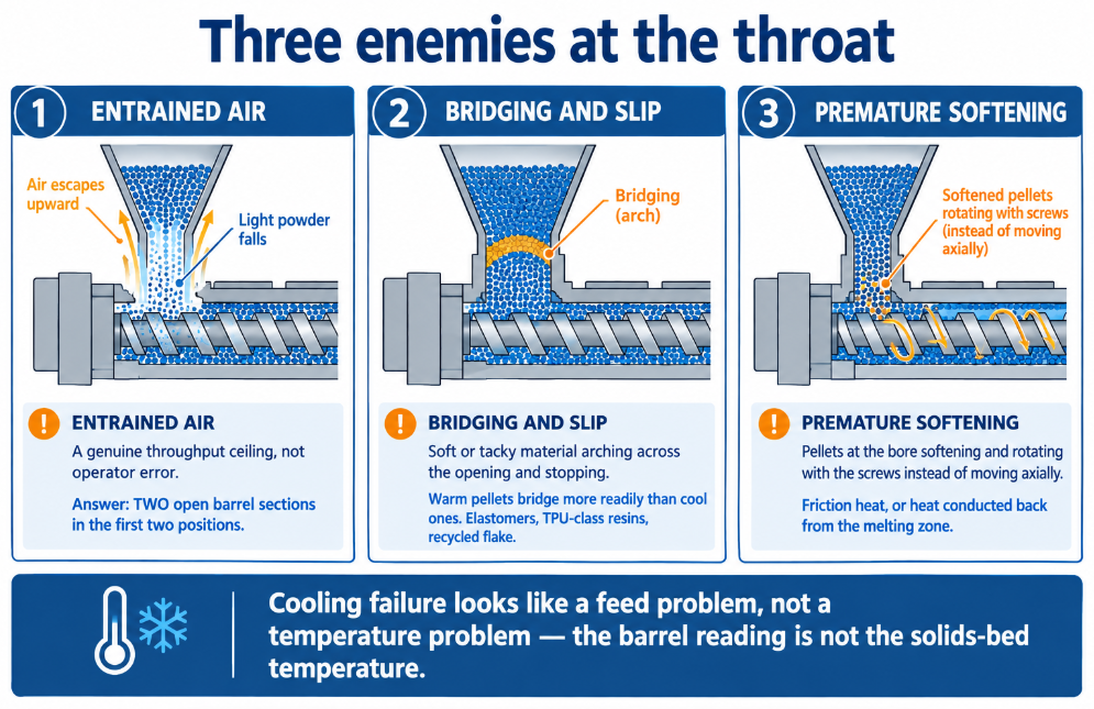
The documented answer: two open barrel sections in the first two positions, giving the air somewhere to leave and the powder more room to enter. Twin-screw feeding of powders is a barrel-layout decision before it is a feeder decision.
2. Bridging and slip. Soft, tacky, or irregular material arches across the throat and stops flowing. Warm pellets bridge more readily than cool ones — another argument for effective feed-section cooling — and elastomers, TPU-class resins and recycled flake are the usual offenders.
3. Premature softening. Covered above: heat, whether from friction or conduction, turns free-flowing solids into a rotating mass.
Screw Elements Through the Feed Barrel
The barrel and the elements inside it are one decision. Through the feed section, configuration favours long-lead conveying elements — open, fast-conveying geometry that gets material away from the throat and clears the opening so more can fall in.
One element-selection caution worth repeating: “SK” type feed elements, whose undercut helps when feeding dry solid ingredients, are not wiped the way the rest of the flight is — so the self-cleaning behaviour that makes co-rotating machines forgiving is partly lost where they’re used. That matters on materials that degrade or on lines that change colour frequently. The broader element logic is in our twin-screw elements guide.
Why Fibers Don’t Go In the Feed Throat
A specific and widely-misunderstood point: shear forces are at a maximum during the solid-to-melt transition, which is exactly where material fed at the main throat ends up. Fibers fed there are essentially ground into powder, and the reinforcement you paid for is gone before the die.
That is why glass and carbon fiber are fed downstream through a side feeder into already-molten polymer, via a combi barrel. The side feeder’s screws stuff the solids into the melt; the extruder screws through the combi barrel run long-lead conveying elements starting about one diameter upstream of the opening. Our when to use side feeding guide covers the decision, and the fiber-length stakes are covered in our EV and energy storage compounding guide.
Feed Barrel Construction and What It Means for Replacement
A twin screw barrel section is typically a liner carrying the figure-eight bore, fitted inside a barrel casing, with cooling channels drilled through the casing and end plates closing them into a circuit. That construction has two consequences buyers meet eventually:
- The liner is the wear part; the casing is the structure. On feed barrels the bore wears more slowly than in the kneading zones, but abrasive feedstock — mineral fillers, regrind with contamination, glass through the throat — does reach it.
- Replacing a press-fitted liner is not trivial, since it means separating it from the casing. Which is why it’s worth knowing at specification time whether a barrel design allows liner replacement or expects whole-section replacement. The general repair-or-replace economics are in our barrel repair vs replacement guide.
When specifying or replacing a feed barrel, the details that matter:
- Opening geometry and position — it must match the feeder arrangement and the barrel layout.
- Cooling circuit — channel layout, condition, and whether it can be cleaned.
- Liner material — matched to the feedstock’s abrasiveness; see bimetallic construction.
- Flange and bore alignment — a feed barrel that doesn’t align with the sections either side creates a step the solids catch on.
Symptoms and What They Point To
| Symptom | Likely cause |
|---|---|
| Can’t reach target rate; feeder calling for more than the throat will take | Feed-section restriction — bridging, air backflow, or softening |
| Powder feed rate limited well below spec | Entrained air — consider a second open barrel section |
| Feeding worsens as the run progresses | Feed-section cooling losing ground to conducted heat; check circuit condition |
| Intermittent surging in the first minutes after startup | Barrel not yet at steady thermal state; cold pellets bridging |
| Material building up around the throat opening | Softening at the bore; cooling or element configuration |
| Fiber reinforcement not delivering expected mechanicals | Fibers fed at the main throat instead of downstream |
| Colour changeover taking far longer than expected | Poorly wiped elements in the feed zone (SK-type undercuts) |
| Feed-zone bore visibly worn on an abrasive compound | Normal; specify liner material for the feedstock, not the polymer |
The feed barrel is the least glamorous section on the machine and the one that decides what the rest of it is allowed to do — because on a starve-fed extruder, everything downstream is configured around a rate the throat has to be able to accept in the first place.
At BLOOM, we manufacture twin screw barrels — feed, closed, combi and vent sections — along with screws and twin-screw elements, built to drawing or reverse-measured from your existing sections, with liner materials matched to your feedstock and full material and dimensional documentation. If your line is feed-rate limited, or a feed section’s cooling or bore is no longer doing its job, send our engineering team your machine make and model, barrel layout, feedstock, and the symptom on WhatsApp and we’ll quote the section you actually need.
References and Further Reading
- How to Configure Your Twin-Screw Barrel Layout, Plastics Technology (K. Russell) — open barrel at Barrel 1 followed by closed barrels; open barrels having fewer heaters and cooling channels while closed barrels provide temperature control on all sides; low-bulk-density powders entraining air that blocks powder flow, and using two open barrel sections in the first two positions; combi barrels at Barrel 4 or 5 for side feeding: https://www.ptonline.com/articles/how-to-configure-your-twin-screw-barrel-layout
- How to Configure Your Twin-Screw Extruder — Part 2, Plastics Technology (K. Russell) — single screws being flood-fed while twin screws are starve-fed with feeders metering material into the feed throat at a steady controlled rate, and the function of the feed section in accepting and conveying solids: https://www.ptonline.com/articles/how-to-configure-your-twin-screw-extruder—-part-2
- Configuring the Twin Screw Extruder: Part 4, Plastics Technology (K. Russell) — shear forces at maximum during the solid-to-melt transition grinding throat-fed fibers into powder, side-feeder and combi-barrel practice, long-lead conveying elements, and the caution that SK-type feed elements are not wiped like the rest of the flight: https://www.ptonline.com/articles/configuring-the-twin-screw-extruder-part-4-
- US Patent 4,832,889 (USPTO) — frictional heat generation softening solids and limiting axial movement in the feed zone, and the resulting need to water-cool the screw and barrel in the throat and feed zones: https://image-ppubs.uspto.gov/dirsearch-public/print/downloadPdf/4832889