China BLOOM manufactures twin-screw elements and barrels for solid-state electrolyte membrane lines — both routes: the dry PTFE-fibrillation process used for sulfide and oxide electrolyte films, and true melt extrusion of polymer-based solid electrolytes (PEO-class hosts with lithium salt and ceramic filler). These are different jobs. The dry route asks the screw to fibrillate half a percent of binder through a bed of moisture-sensitive ceramic without degrading it. The melt route asks for deagglomeration and distributive mixing of high filler loadings, with residence time held short enough that the polymer host survives — and with die flow and cooling controlling the crystallinity that ultimately sets ionic conductivity. This page covers what each route demands from the hardware.
The post By the BLOOM Engineering Team
⚠️ A note on maturity: solid-state manufacturing is still consolidating. Formulations, thicknesses, and process windows are moving targets, and specifications here reflect published research rather than settled industry standards. We build to your process, not to a template.
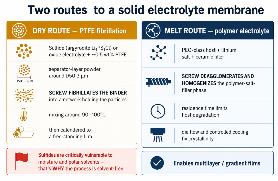
Two Routes, Two Different Screws
| Dry route (PTFE fibrillation) | Melt route (polymer electrolyte) | |
|---|---|---|
| Materials | Sulfide (argyrodite Li₆PS₅Cl) or oxide electrolyte + ~0.5 wt% PTFE | PEO-class polymer host + lithium salt + ceramic filler |
| What the screw does | Fibrillates the binder into a network holding electrolyte particles | Deagglomerates filler and homogenizes the polymer–salt–filler phase |
| Temperature driver | Enough heat to fibrillate PTFE (mixing around 90–100°C in published work), not enough to degrade the electrolyte | Melt the polymer host, without exceeding its degradation limit |
| Critical constraint | Sulfides are critically vulnerable to moisture and polar solvents | Residence time — it limits degradation of PEO or other hosts |
| Downstream | Calendering to a free-standing film | Die flow and controlled cooling set crystallinity |
| Why it’s chosen | Avoids solvents that damage sulfide ionic conductivity | Continuous, scalable, enables multilayer/gradient films |
The Dry Route: Fibrillating Binder Through a Sensitive Ceramic
The dry process mixes electrolyte powder and binder with no solvent, then presses or calenders the result into a film. PTFE fibrillates under shear and bonds the electrolyte particles together — the same mechanism used in dry electrode production, applied here to the separator layer instead of the cathode.
What makes the membrane version its own problem:
- The reason the process exists is solvent avoidance. Sulfide electrolytes lose ionic conductivity on contact with polar solvents, which is precisely why researchers moved to dry processing. Any moisture the hardware introduces defeats the point.
- Binder loading is tiny. Published work uses around 0.5 wt% PTFE — the screw must build a continuous network out of almost nothing, distributed evenly through the ceramic.
- Particle size is fine and deliberate. Argyrodite for the separator layer is used at around D50 ≈ 3 µm (versus ~1 µm in the cathode composite) — fine powder that flows, packs, and abrades differently from a polymer melt.
- Over-shearing costs you twice. Too little shear leaves the film weak; too much can degrade the electrolyte and drive the binder chemistry in unwanted directions. The shear window is real, and it’s set by kneading configuration — the same trade-off mapped in detail on our dry electrode page.
Hardware implications: wear-resistant, non-shedding element surfaces; fully swept geometry (dry powder finds every pocket); and construction and packaging fit for dry-room handling.
The Melt Route: Where the Screw Does Conventional Work Under Unconventional Constraints
Polymer solid electrolytes are extruded much more like a filled compound — and this is where classic twin-screw design thinking applies directly. Published process descriptions put it plainly: the screw supplies the distributive and dispersive mixing needed to deagglomerate powders and couple surface-modified particles to the polymer–salt phase, while residence-time control limits degradation of PEO or other hosts. Die flow and controlled cooling then fix crystallinity and particle spacing, which set tortuosity and percolation.
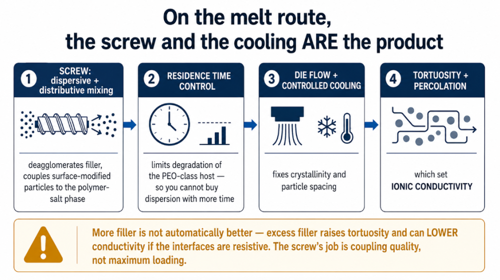
Unpack that and you get the specification:
- Deagglomeration is dispersive work. Ceramic filler agglomerates raise interfacial impedance and create weak spots — they must be broken up, which means kneading elements with real shear capability. See choosing a mixing section.
- But residence time caps how much shear you can spend. PEO-class hosts degrade with heat and time, so the screw can’t buy dispersion by simply working the melt longer. Short, efficient, well-configured — not long and brutal.
- More filler is not automatically better. Excess filler raises tortuosity and can lower ionic conductivity if the interfaces are resistive. The screw’s job is coupling quality, not maximum loading.
- Cooling is part of the product. Because controlled cooling fixes crystallinity and particle spacing — and those set the ion transport path — the thermal design of the barrel and downstream is as much a product parameter as the mixing is. See our barrel temperature control hardware guide.
- Multilayer and gradient films are on the table. The same platform can produce a stiff, filler-rich layer facing the lithium anode and a more conductive, filler-lean layer facing the cathode composite — which means coextrusion with matched, consistently-performing screws.
The Constraints Both Routes Share
Moisture exclusion. Sulfide electrolytes are critically vulnerable to moisture — this isn’t a quality preference, it’s a safety and performance requirement, and it means dry-room operation, sealed feeding, and parts that arrive fit for that environment. Note the contrast with most extrusion troubleshooting: here you are not venting moisture out, you are keeping it from ever getting in.
No shed metal. Metallic debris in an electrolyte membrane is a potential internal short — the same non-negotiable that governs separator lines. Wear surfaces must be metallurgically sound so they wear slowly and cleanly, and geometry must leave nothing anywhere to accumulate.
Abrasion from ceramic loading. Both routes run high solids content of hard inorganic material, which puts them in the same abrasion class as heavily-filled compounding — the case for bimetallic or tungsten-carbide-bearing construction rather than nitrided bores.
Thin-film targets. The whole point of better membrane processing is thinner films — conventional cold-pressed sulfide separators run hundreds of microns to a millimetre, which caps cell energy density. Thinner films magnify every uniformity defect the screw passes through.
What We Supply
| Item | Construction |
|---|---|
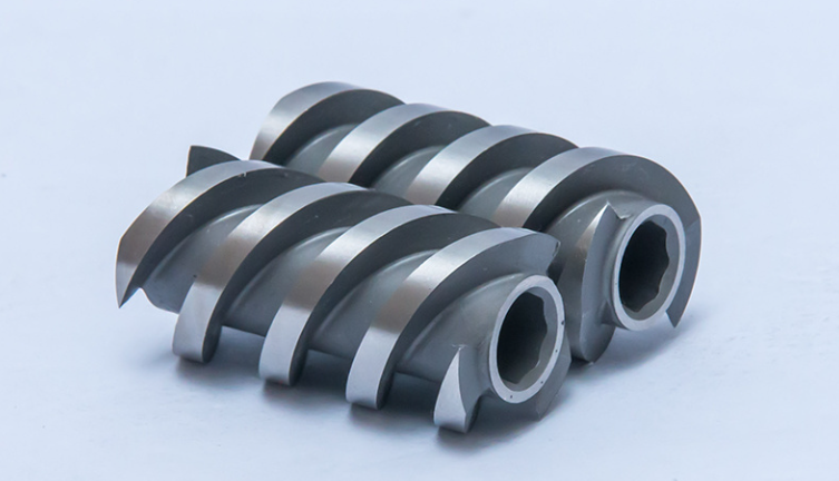
| Twin-screw elements (kneading, conveying, mixing) | Tool-steel and powder-metallurgy grades; wear-resistant, non-shedding surfaces |
| Twin-screw barrels and liners | Bimetallic or carbide-bearing liners; segmented configurations |
| Single screws and barrels for polymer-route lines | Low-shear, streamlined, temperature-controlled designs |
| Element sets to your configuration | Built to your kneading sequence, or reverse-measured from existing sets |
| Reverse engineering | From worn parts or drawings, with full dimensional reports |
Every part ships with material certificates, hardness reports, and dimensional records — see our acceptance inspection checklist. Element fundamentals are in our twin-screw elements guide.
Frequently Asked Questions
We’re at pilot scale and our process is still changing. Can you work with that? Yes — that’s normal in this field. We build to your current configuration and reverse-measure or re-specify as your process evolves. We don’t have a fixed “solid-state screw” to sell you.
Can the same elements run cathode composite and separator layer? Sometimes, but the duties differ: the separator layer uses coarser electrolyte powder and almost no binder, while the cathode composite carries active material at high loading. Where a line runs both, dedicated configurations usually outperform a compromise.
How do you handle the contamination requirement? The same way we do for separator and dry electrode lines: wear surfaces specified to resist abrasion without shedding, fully swept geometry, and documentation with every part.
Do you supply for polymer (PEO-type) electrolyte extrusion as well as dry sulfide processing? Yes — those are different screw designs, and we’d want your formulation, host polymer, filler loading, and temperature profile to specify either one properly.
Solid electrolyte membranes ask a twin-screw extruder to do precise work on materials that punish imprecision — a binder network built from half a percent of polymer, or a filler dispersion that must be thorough without the residence time to be gentle — and in both cases the hardware has to do it while adding neither moisture nor metal.
If you’re developing or scaling a solid electrolyte membrane line, send our engineering team your route (dry or melt), electrolyte chemistry and loading, host polymer if applicable, extruder model, and element configuration on WhatsApp and we’ll specify elements and barrels built for it — with the documentation battery production requires. See also our dry battery electrode page and battery separator page.
References and Further Reading
- Solvent-free extrusion of polymer-based solid-state electrolytes: Formulation, processing and modeling, Chemical Engineering Journal (ScienceDirect), 2026 — the screw supplying distributive and dispersive mixing to deagglomerate powders and couple surface-modified particles, residence-time control limiting host degradation, die flow and controlled cooling fixing crystallinity and particle spacing, and multilayer/gradient film capability: https://www.sciencedirect.com/science/article/pii/S1385894726044165
- Optimization of PTFE fibrillation in dry electrode process for scalable all-solid-state battery manufacturing, Journal of Power Sources (ScienceDirect), 2025 — sulfide electrolytes’ critical vulnerability to moisture and polar solvents, and argyrodite Li₆PS₅Cl used at D50 ≈ 1 µm for cathode composite and 3 µm for the separator layer: https://www.sciencedirect.com/science/article/abs/pii/S0378775325017616
- Interfacial Challenges and Strategies toward Practical Sulfide-Based Solid-State Lithium Batteries, Energy Material Advances — the dry process rationale (avoiding solvent damage to sulfide ionic conductivity) and PTFE fibrillating under shear to bond electrolyte materials: https://spj.science.org/doi/10.34133/energymatadv.0022