A vent barrel’s hard problem is not extracting gas — it is extracting gas while the melt stays where it belongs. Put an opening in a pressurized barrel and vapour leaves; but under vacuum, or at high vapour velocity, or with a low-viscosity melt, polymer comes with it. And before any of that can work, the vacuum has to be isolated from the rest of the machine by a melt seal made from the screw elements themselves — because a vent port open to the feed throat is not a vacuum zone, it’s a leak. This guide covers atmospheric and vacuum venting, the sealing that makes it possible, the three vent-port designs, multi-vent strategy, and what the vent section means when you’re specifying or replacing barrels.
By the BLOOM Engineering Team
Atmospheric and Vacuum Venting Do Different Jobs
| Atmospheric vent | Vacuum vent | |
|---|---|---|
| Pressure at the port | Ambient | Below ambient, sometimes deep vacuum |
| Removes | Entrained air, easily-flashed moisture, high-concentration volatiles | Dissolved volatiles, solvents, monomers, residuals down to low ppm |
| Typical position | Early — near the feed, or just upstream of a side feeder | Downstream, in the melt |
| Melt carry-over risk | Low | High — this is what vent stuffers exist for |
| Usual role | Bulk removal, first pass | Finishing to specification |
Most compounding processes use both — atmospheric vents to dump the easy volume, vacuum vents to reach the residual level the product actually requires. And machines are routinely equipped with multiple vacuum vents for removing large volumes of solvent or monomer while still producing low residual volatile levels in the finished pellet.
One documented laboratory configuration illustrates how far this scales: a 25 mm, 40 L/D co-rotating twin screw with six vents — three atmospheric (on the side feeder, barrel 1 and barrel 4, connected to a solvent recovery system under only about 25 mm Hg of assist) and three vacuum vents at barrels 5, 7 and 9. Devolatilization at that level is a staged process, not a single port.
The Seal Is the Whole Trick
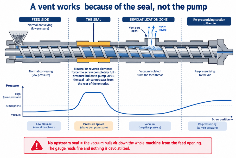
A vacuum vent only works if the vacuum zone is isolated. That isolation is built from screw elements, not from gaskets:
- The upstream seal is created by neutral or reverse compounding elements, a blister, a cylinder, or another restrictive element in the screws, so that air cannot pass from the rear of the extruder into the devolatilization zone.
- A neutral or reverse element forces the screw to be completely full at that seal — and full for some turns upstream of it — generating the pressure needed to pump over the seal.
- That full, pressurized plug isolates the vacuum of the devolatilization zone from the feed throat and the other zones.
So the vent barrel and the screw configuration are a single design. A perfectly built vent barrel with no upstream seal simply pulls air down the length of the machine from the feed opening, and the vacuum gauge tells you a comforting lie while nothing is being devolatilized.
Downstream of the vent, the melt must be re-pressurized to the die — which is the same two-stage pressure architecture described in our vented screw guide, applied here with the barrel section in view rather than the screw.
Three Vent-Port Designs
A range of vent-port designs exists for co-rotating twin screws, developed to suit different materials and volatile loads:
1. Elongated vent barrel. The simplest approach: a longer opening gives vapour more escape area and lowers vapour velocity through the port, which reduces the tendency to entrain melt. Where volatile load is moderate and melt viscosity is reasonable, more open length is often the cheapest fix available.
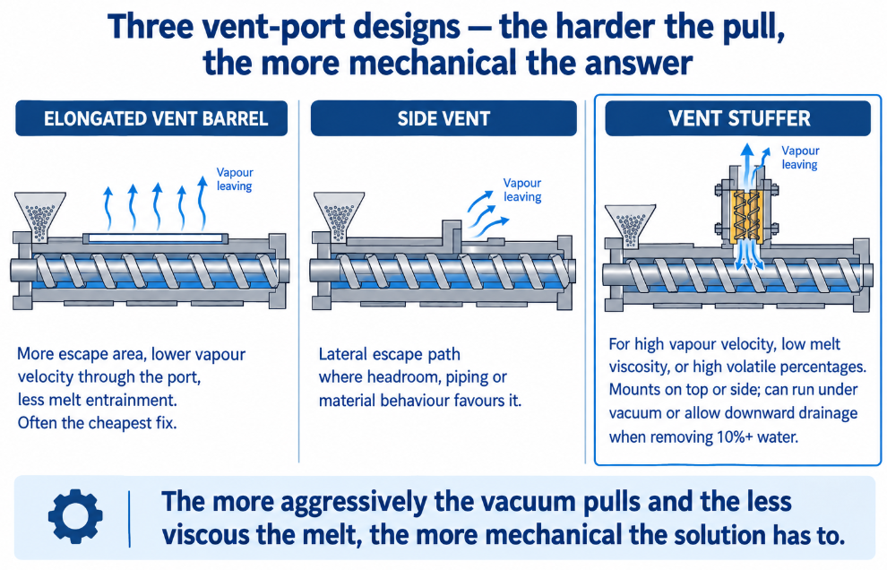
2. Side vents. The port is placed on the side of the barrel rather than the top. Useful where headroom, piping, or the behaviour of the material favours a lateral escape path.
3. Vent stuffers. For the hardest cases — high vapour velocity, low melt viscosity, or high volatile percentages — a mechanical co-rotating twin-screw auger is installed within the vent opening. It pushes back any material that would otherwise fly out of the extruder under vacuum, while still allowing gas to travel axially through its own screws and out. Vent stuffers mount on the side or on the top, and can be designed either to operate under vacuum or to allow downward discharge — the latter mattering when something like 10%+ water is being removed and you want it to drain rather than be pulled through a vacuum system.
The selection logic is straightforward: the more aggressively the vacuum pulls and the less viscous the melt, the more mechanical the solution has to be.
Multiple Vents, and Why
Each additional vent stage lowers residual volatiles substantially — venting in series is far more effective than trying to do everything at one port, because each stage works on a lower starting concentration. Practical patterns:
- Atmospheric first, vacuum after. Dump the bulk where it’s free; use vacuum for what’s left.
- A slight assist on atmospheric vents. The laboratory example above applied roughly 25 mm Hg to its “atmospheric” vents purely to help the solvent move toward recovery — a small measure with a meaningful effect.
- Stripping agents upstream of a vent. Injecting water, nitrogen or CO₂ before a kneading section and vent raises the effective removal by giving dissolved volatiles something to leave with. Barrel temperature at the downstream end is then set above the stripping agent’s boiling point but below the material’s heat-resistance limit — a window that has to be held.
The Back Vent: A Detail Worth Knowing
There’s a specific configuration that catches people out. When filler is introduced through a side feeder, it carries air and moisture with it. An atmospheric back vent placed on the barrel segment immediately upstream of the side-feed opening gives that air an escape route, slightly densifying the filler as it enters.
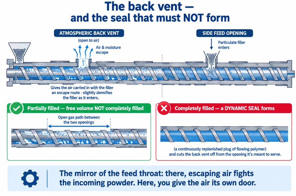
The catch is in the screws between the two openings: that section must be configured so the melt does not completely fill the free volume — because a full channel would form a dynamic seal (a continuously-replenished plug of flowing polymer) and cut the back vent off from the side-feed opening it’s supposed to serve. Getting that right is an element-configuration decision that lives or dies with the barrel layout around it; see our twin-screw elements guide and when to use side feeding.
It is, incidentally, the mirror of the feed barrel’s air problem: at the main throat, escaping air fights the incoming powder; at a side feeder, you give the air its own door.
What a Vent Barrel Must Have — and What Goes Wrong
Specification points when buying or replacing a vent section:
- Opening geometry and length — matched to the vapour volume and to whether a stuffer will be fitted.
- Provision for a stuffer — mounting face, bore, and alignment; retrofitting a stuffer to a barrel that wasn’t designed for one is rarely economical.
- Vacuum connection and condensate handling — the plumbing outside the barrel decides whether what you extract stays extracted.
- Cooling circuit — vent sections still need thermal control; see our barrel temperature control guide.
- Liner material — abrasive and corrosive feedstocks reach the vent zone too; see bimetallic construction.
- Surface condition around the opening — burrs, steps and misalignment at the port edge are where material catches and builds.
And the recurring failure: port plugging. Material that creeps into the opening cools, degrades and builds a crust that progressively closes the vent — after which volatiles stay in the product while the gauge still reads vacuum. Causes include excessive fill upstream, vapour velocity dragging melt, an undersized port, temperature problems at the port, and worn clearance letting the melt behave differently than the design assumed.
One boundary worth restating: a vent is not a dryer. Hygroscopic resins like PET and nylon carry moisture inside the pellet that does its damage during melting — before and while the vent can act. Venting removes what’s free to leave; drying removes what’s bound. See drying PET and drying nylon.
Symptoms and What They Point To
| Symptom | Likely cause |
|---|---|
| Residual volatiles above spec, vacuum gauge reads fine | Port plugging, or no effective upstream seal — vacuum pulling air from the feed end |
| Melt escaping the vent port | Vapour velocity or low viscosity dragging melt — needs a longer port or a stuffer |
| Vacuum can’t be pulled at all | Upstream seal missing or broken; leak at the port, piping or condenser |
| Vent performance falls as the run progresses | Progressive plugging; condensate return |
| Product voids or bubbles despite venting | Volatiles generated downstream of the vent, or moisture that needed drying |
| Filler feeding poorly through a side feeder | Air has nowhere to go — consider an atmospheric back vent upstream |
| Vent problems worsening over months | Wear — changed fill behaviour and clearance; check with our wear limit calculator |
A vent barrel is an opening with a job that only works because of everything around it — a seal built from elements upstream, a re-pressurizing section downstream, and a port sized so vapour leaves faster than melt can follow — which is why venting problems are so rarely solved at the vacuum pump.
At BLOOM, we manufacture twin screw barrels — feed, closed, combi and vent sections — plus screws and twin-screw elements, built to drawing or reverse-measured from your existing sections, with liner materials matched to your process and full documentation. If you’re fighting residual volatiles, melt escaping a port, or a vent section that’s no longer clean, send our engineering team your machine make and model, barrel layout, material and volatile load, and the symptom on WhatsApp and we’ll quote the section you need.
References and Further Reading
- Solve Venting Problems on Twin-Screw Compounding Extruders, Plastics Technology — atmospheric versus vacuum vent openings and the use of both in most compounding processes, multiple vacuum vents for high solvent and monomer loads, and the three vent-port families (vent stuffers, elongated vent barrels, side vents), with mechanical twin-screw stuffers preventing melt from being pulled out of the screw channels under vacuum: https://www.ptonline.com/articles/solve-venting-problems-on-twin-screw-compounding-extruders
- Demystifying the Devolatilization Process, Plastics Technology — the upstream seal formed by neutral or reverse elements, a blister or a cylinder so air cannot pass from the rear of the extruder into the devolatilization zone, forcing a completely full screw at the seal and isolating the vacuum from the feed throat: https://www.ptonline.com/blog/post/demystifying-the-devolatilization-process
- US Patent 6,949,622 (USPTO) — a 25 mm, 40 L/D co-rotating twin screw with six vents: three atmospheric vents on the side feeder, barrel 1 and barrel 4 under roughly 25 mm Hg of assist to a solvent recovery system, and three vacuum vents at barrels 5, 7 and 9: https://image-ppubs.uspto.gov/dirsearch-public/print/downloadPdf/6949622
- US Patent 11,027,476 (USPTO) — an atmospheric back vent on the barrel segment immediately upstream of a secondary feed opening letting moisture and air accompanying particulate filler escape, with the intervening screw section configured not to completely fill the free volume so that no dynamic seal forms: https://image-ppubs.uspto.gov/dirsearch-public/print/downloadPdf/11027476