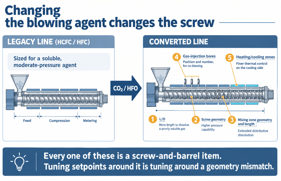
Switching an XPS line from HCFC or HFC blowing agents to CO₂ and HFO blends is not a formulation change — it is a machine change. Extruder builders who ran the transition report having to modify screw L/D, screw geometry, the geometry and length of the mixing zone, the position and number of gas-injection bores, and the number of heating and cooling zones — because alternative gases need different pressures and temperatures to dissolve, and CO₂ in particular dissolves poorly in polystyrene, driving die pressure past what a legacy screw can manage. This guide covers what XPS board demands of the screw and barrel, what the blowing-agent transition did to those demands, how lines are configured by output, and the wear and corrosion the additive package brings.
By the BLOOM Engineering Team
What XPS Board Extrusion Looks Like in Numbers
| Parameter | Typical value |
|---|---|
| Product | Rigid insulation board, ~25 mm (1 in) thick, widths above 500 mm |
| Density | ~22–48 kg/m³ (1.4–3 pcf); a common target around 36 kg/m³ |
| Foaming die temperature | 110–130°C |
| Foaming die pressure | 800–1,200 psi (5.5–8.3 MPa) |
| Cell size | ~0.005–0.6 mm; open-cell content below 30% |
| R-value | ~4–7 per inch |
| Blowing agent loading | ~4% CO₂ alone, up to ~8% total in CO₂/HFO/hydrocarbon blends |
| Nucleator | Talc, typically 0.2–2% |
| Output | Pilot ~100–160 kg/h; industrial tandem lines to ~2,000 kg/h |
Two of those numbers govern everything: the die must be at 110–130°C, and the melt reaching it must still hold the blowing agent in solution at 800–1,200 psi. The polymer left the primary extruder far hotter than that — so between the injection point and the die, the line has to dissolve the gas, cool the melt by roughly 100°C, and never let pressure fall enough for the gas to come out early. That’s the tandem cooling job covered in our foam extrusion screw guide; XPS is where it’s done at building-materials scale.
The Blowing Agent Transition — and Why It Was a Screw Problem
| Era | Agent | Process character | Why it was phased out |
|---|---|---|---|
| Historic | CFC-12 | Highly soluble, easy to process, excellent insulation | Ozone depletion |
| Transitional | HCFC-142b | Still processable | Ozone depletion |
| Recent | HFC-134a, HFC-152a | Processable, non-ozone-depleting | High global warming potential |
| Current | CO₂ ± HFO (1234ze, 1336mzz) ± hydrocarbons | CO₂: cheap, non-flammable, negligible GWP — but poorly soluble in PS | — |
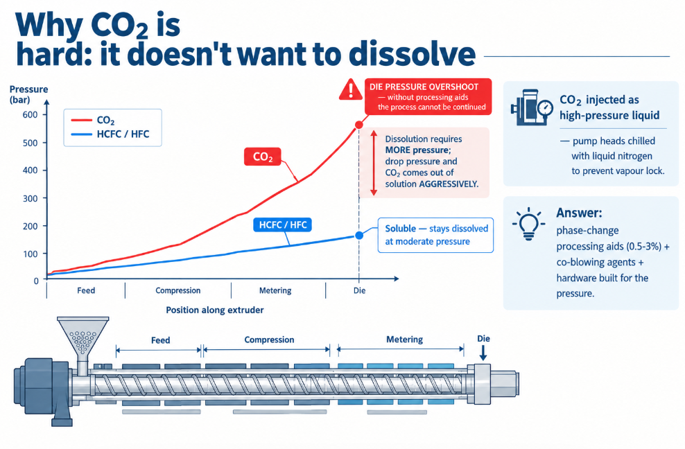
The processing consequence of CO₂ is documented plainly in the patent literature: run a conventional line on CO₂ without processing aids and the process cannot be continued because of die pressure overshooting. CO₂’s low solubility means it needs more pressure to stay dissolved, and its high vapour pressure means it comes out of solution aggressively the moment pressure drops. Formulators answer with phase-change processing aids (0.5–3%) and co-blowing agents; machine builders answer with hardware.
What actually changed on the extruders, per one builder’s transition programme:
- Screw L/D — more length to dissolve a less soluble gas.
- Screw geometry — pressure capability, because the melt seal and the dissolution zone both run at higher pressure.
- Mixing zone geometry and length — CO₂ needs more distributive mixing time to reach a true solution rather than a dispersion of bubbles.
- Position and number of gas-injection bores — CO₂/HFO co-blowing often means separate injection points, and CO₂ is injected as a high-pressure liquid (pump heads chilled with liquid nitrogen to prevent vapour lock).
- Number of heating/cooling zones — finer thermal control on the cooling side, because CO₂-blown melt needs to arrive at the die cooler and more uniform than HCFC-blown melt did.
Every one of those is a screw-and-barrel item. A plant that swaps blowing agents on legacy hardware and then chases the resulting pressure and cell-structure problems with process settings is trying to tune its way around a geometry mismatch — the same trap as running the wrong compression ratio and adjusting temperatures, as discussed in our screw design guide.
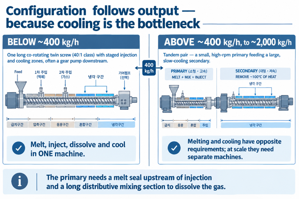
Line Configuration Follows Output
| Output | Configuration | Why |
|---|---|---|
| Below ~400 kg/h | Slow-running co-rotating twin screw, single machine | Enough cooling capacity in one long (40:1 class) barrel with staged injection and cooling zones |
| Above ~400 kg/h, to ~2,000 kg/h | Tandem — high-rpm primary (melt, mix, inject) feeding a large, slow cooling secondary | Melting and cooling have opposite requirements; at scale they must be separated into different machines |
The threshold exists because cooling is the bottleneck. A single machine can melt, inject, dissolve, and cool a few hundred kilos an hour; beyond that, the cooling half of the job needs its own extruder with its own surface area and its own slow speed — see the tandem cooling screw logic. Twin-screw single-machine lines often run a gear pump downstream to hold barrel pressure high enough for dissolution regardless of screw speed.
For the primary extruder on a tandem line, the specification is: complete melting, a robust melt seal upstream of the injection port (a restrictive element that keeps the fully-filled melt from letting gas escape backward), then a long distributive mixing section to dissolve the agent. See choosing a mixing section for why distributive rather than dispersive elements do this job.
The Additive Package: Wear and Corrosion in a “Clean” Polymer
Polystyrene is a gentle material. An XPS formulation is not:
| Additive | Typical loading | What it does to the hardware |
|---|---|---|
| Talc nucleator | 0.2–2% | Abrasive mineral — the primary wear driver, especially at the injection/mixing zone where the melt is being worked |
| Flame retardant | ~1% (brominated, now largely polymeric types) | Halogenated — potential acidic by-products at temperature; corrosion-aware surfaces on continuous lines |
| Infrared attenuator | ~0.5% (graphite, carbon black) | Adds abrasion; also a contamination concern if surfaces shed |
| Recycled XPS / regrind | Variable | Unpredictable filler and contamination; higher gel risk |
| CO₂ + any moisture | — | Mild carbonic acid environment at pressure |
None of these individually looks severe. Together, on a line running continuously for weeks at building-products volume, they put the screw and barrel into the same wear class as lightly-filled compounding — which is why XPS lines specify bimetallic barrels and hardfaced flights as a baseline, and why brominated flame-retardant duty argues for corrosion-aware surfaces of the kind on our nickel base alloy page.
And the wear signature is foam-specific: clearance opening on the cooling screw lets melt recirculate and re-shear — adding heat the cooling extruder exists to remove. So an XPS line’s first sign of wear is usually a creeping foaming temperature and coarsening cells, well before output falls. Check against our wear limit calculator when the cell structure starts drifting.
Symptoms and What They Point To
| Symptom | Likely cause |
|---|---|
| Die pressure overshooting, unstable | CO₂ not fully dissolved — insufficient mixing length or pressure; processing aid level |
| Coarse or irregular cells | Melt too hot at the die — cooling capacity, screw speed, or worn clearance re-shearing |
| Blowing agent detected at the feed throat | Melt seal failure — worn restrictive element, or fill insufficient upstream |
| Density drifting over a run | Injection metering, or output instability |
| Cell structure coarsening over months, no process change | Wear — recirculation on the cooling screw, or fouled barrel cooling channels |
| Board surface defects, voids | Degraded material from stagnation; unmelts; gel from regrind |
| Cannot reach target density with CO₂ | Line’s cooling or pressure capability was sized for the old agent |
That last row is the one to take seriously. A line designed for HCFC or HFC agents has a cooling and pressure envelope sized for those agents. Running CO₂ inside that envelope produces exactly the complaints above — and the fix is the hardware list at the top of this page, not another round of setpoint changes.
XPS is where the blowing-agent transition stopped being a chemistry story and became a screw story — because the new agents ask the primary screw to dissolve a gas that doesn’t want to dissolve, ask the cooling screw to remove more heat than before, and ask both to do it at building-products throughput without adding shear heat back in.
At BLOOM, we build extruder screws and barrels for XPS board and foam sheet lines — primary screws with melt-seal and extended distributive dissolution sections sized for CO₂ and HFO agents, deep-channel cooling screws, cooled barrels, and wear grades matched to your talc, flame retardant, and regrind loading. If you’re converting a line to low-GWP blowing agents, or fighting pressure overshoot and cell-structure drift since you did, send our engineering team your blowing agent system, extruder diameters and L/D, output, and current die conditions on WhatsApp and we’ll tell you what the geometry needs to become.
References and Further Reading
- US Patent 10,676,581 (USPTO) — XPS board extrusion with CO₂ and HFO-1234ze at 100–160 kg/h, foaming die at 110–130°C and 800–1,100 psi, ~3.7–4.3% CO₂, and the finding that without phase-change processing aids the process could not be continued due to die pressure overshooting: https://image-ppubs.uspto.gov/dirsearch-public/print/downloadPdf/10676581
- Foam XPS Board, Union Extrusion — the engineering modifications required to adapt XPS lines to environment-friendly blowing agents (screw L/D, screw geometry, mixing-zone geometry and length, gas-injection bore position and number, heating/cooling zone count), and configuration by output: co-rotating twin screw below 400 kg/h, tandem above it to 2,000 kg/h: https://unionextrusion.it/en/espanso/pannello-espanso-in-xps/
- EP 3,166,996 A1 (European Patent Office) — XPS foams using CO₂ as the major blowing agent (59 mol% or more) with HFO and HFC co-blowing agents, die temperature 110–130°C and die pressure 800–1,200 psi: https://patents.google.com/patent/EP3166996A1/en