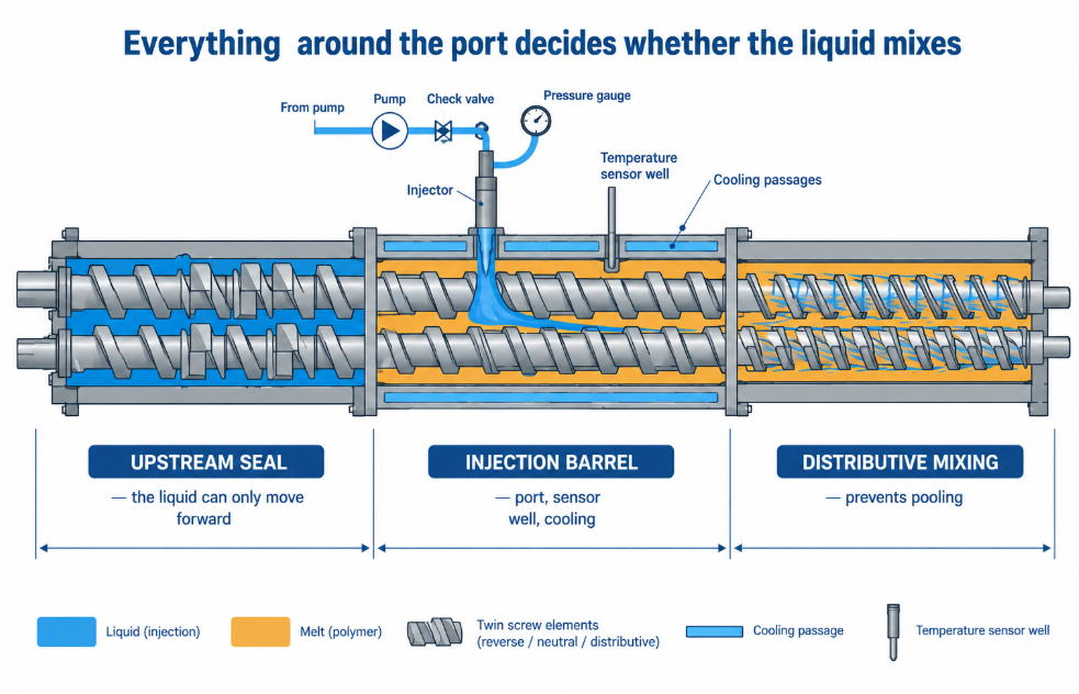
A liquid injection barrel is a closed barrel section with one or more ports through which a pump meters liquid straight into the process — and getting the liquid in is the easy part. The hard part is everything after the port: keeping the liquid from pooling in the screw channels instead of mixing, keeping it from running back toward the feed, keeping it from lubricating the screws into losing their mixing action, and keeping the port itself from clogging or corroding. All of that is decided by where the barrel sits in the layout, what the screw elements do around it, and how the port hardware is built. This guide covers the injection-position decision, the pressure logic behind it, the pooling problem, the port hardware, and what to specify when buying or replacing an injection section.
By the BLOOM Engineering Team
Why Twin Screws Take Liquids Downstream at All
Twin screw process sections are modular: barrels are configured as plain, vented, side-stuffing, liquid-drain, and liquid-addition sections. What makes downstream liquid addition practical is the starve-fed pressure profile — with feeders setting the rate, much of the process section runs at near-zero pressure, and the local pressure at any point is set by the screw design. That’s what lets liquids enter through injection ports well away from the feed throat, the same way fillers enter through side stuffers.
It also means the rate logic is the same as for solids: pumps and feeders set what goes in; screw speed sets how it’s worked. A liquid injection problem is rarely solved by changing screw speed alone.
What Goes In Through an Injection Barrel
| Liquid | Typical purpose | Injection consideration |
|---|---|---|
| Peroxide and other initiators | Visbreaking, crosslinking, grafting | Reactive — position and residence time set how far the reaction goes; see reactive grafting on tab sealant lines |
| Mineral and process oils | Oil extension of TPEs; separator formulations | High loadings pool and lubricate — distributive mixing and staging matter; see battery separator lines |
| Plasticizers | Flexible compounds | Lubricating effect reduces shear downstream |
| Water, N₂, CO₂ as stripping agents | Carry volatiles out at a following vent | Injected upstream of a kneading section and vent; see the vent barrel |
| Liquid colour and additive concentrates | Colour, stabilizers, slip | Small volumes — metering accuracy dominates |
| Silanes, coupling agents | Grafting, filler coupling | Moisture-sensitive; closed downstream injection keeps them away from atmosphere |
| Molten low-melting materials | Waxes, low-Tg melts fed as liquids | Heated lines and heated injector |
Where to Inject: The Position Decision
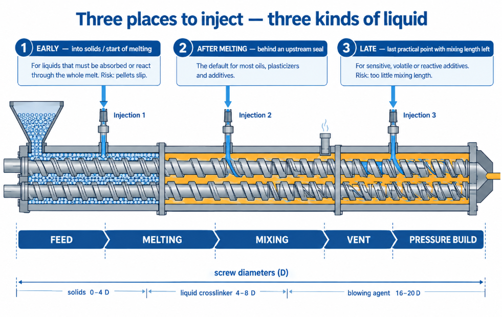
There’s no single right answer — there are three positions, each suited to different liquids:
| Position | When it’s right | The risk |
|---|---|---|
| Early (into solids or the start of melting) | Liquids meant to be absorbed into the polymer or to react through the whole melting history | Liquid wets the pellets and makes them slip — solids conveying and melting can suffer |
| After melting, behind an upstream seal | Most oils, plasticizers, and additives; the general default | Needs a restrictive element upstream so liquid can’t migrate back toward the feed |
| Late (the last practical point before the die, with enough length left to mix) | Sensitive, volatile, or reactive additives you want exposed to heat for as short a time as possible | Too late and there isn’t enough mixing length left |
One documented co-rotating configuration shows how deliberate the placement is: solids fed within the first 4 screw diameters, a liquid crosslinking agent introduced in a dedicated liquid injection barrel element between 4 and 8 diameters, and a chemical blowing agent side-stuffed between 16 and 20 diameters — each ingredient positioned for the processing history it needs.
At the other end, downstream injection has a specific rationale documented in additive-delivery practice: it holds off the addition to the last possible moment while still leaving adequate time for thorough mixing, so the additive is delivered in precise proportion to output — and injecting directly into a closed barrel allows materials that are chemically sensitive to the atmosphere to be added without exposure.
The Pressure Question
Two facts pull against each other:
- Injecting into a near-zero-pressure zone is easy — the pump needs little pressure to deliver.
- But a liquid in a partially filled channel can travel — including back upstream toward the feed throat if nothing stops it.
The standard resolution is the same idea used at vents: a restrictive section upstream of the injection point — reverse or neutral kneading, or another restrictive element — keeps the channel full there, so injected liquid has nowhere to go but forward. Our vent barrel guide covers how that seal is built.
Liquids that would flash or come out of solution at low pressure — volatile agents, and above all gases and supercritical fluids — are the exception: they go into a filled, pressurized zone behind a melt seal, which is the foam-extrusion case covered in our foam extrusion screw guide.
Pooling and Lubrication: Why Liquids Don’t Mix Like Solids
Liquid additions fail in two characteristic ways:
Pooling. A low-viscosity liquid injected into a viscous melt doesn’t spread by itself — it collects in the screw channels and travels as a separate phase. High liquid-phase mixing benefits from specialty high-division-rate distributive elements that prevent pooling of the liquid in the screws; narrow kneading elements that divide and recombine the melt rapidly are the relevant tool, far more than wide, dispersive kneaders. See our mixing section selection guide and twin-screw elements guide.
Lubrication. Oils and plasticizers reduce melt viscosity and wet the screw and barrel surfaces. Downstream of the injection point, the same elements deliver less shear than they did upstream — so a configuration that mixed well before a liquid addition may mix poorly after it. Large liquid fractions are therefore commonly split across more than one injection point, each followed by its own distributive section, so the melt never has to absorb the whole charge at once.
The practical test: if the product shows streaks, surface bleed, or liquid exuding at the die, the liquid went in but never truly mixed.
The Port Hardware
The injection section is only as good as the hardware at the port:
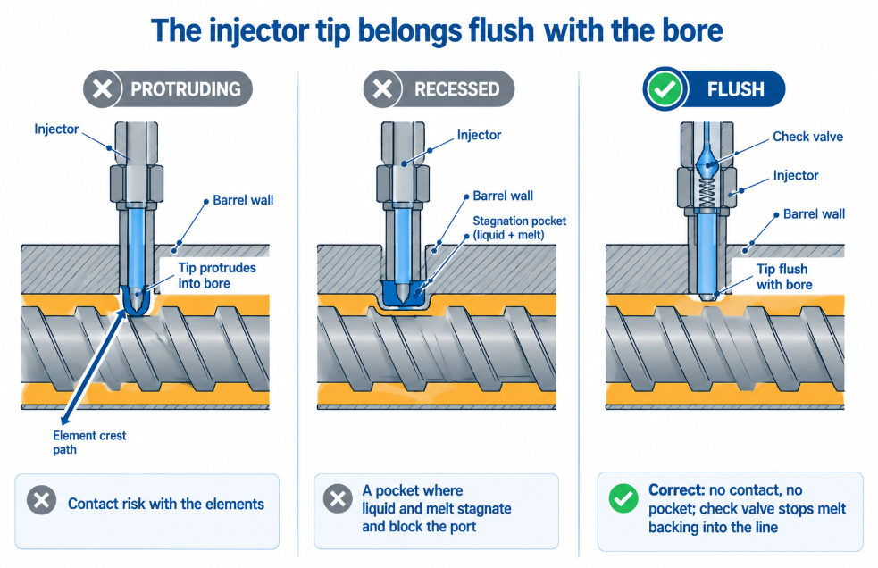
- Injector tip flush with the bore. A tip that protrudes into the bore risks contact with element crests; a tip that sits recessed leaves a pocket where liquid and melt stagnate, degrade, and eventually block the port.
- Check valve at the injector. Stops melt from backing into the liquid line when pump pressure drops or the pump stops.
- Positive-displacement metering. Piston, gear, or diaphragm pumps — sized for accuracy at your flow rate — with flow verified by mass (loss-in-weight or a mass flow meter) where ratio accuracy matters.
- Pressure gauge and bleed point on the line, so a blocked tip is seen as rising line pressure before it becomes an off-spec batch.
- Heated, insulated lines for viscous liquids and molten feeds; a line that cools lets the liquid thicken, and the delivered rate drops even though the pump is running.
- A temperature sensor well and cooling circuit in the barrel element — documented liquid injection barrel elements integrate the injection port, a sensor well, and cooling channels in one section, because the local temperature at the port matters for both the liquid and the melt.
- A closing plug for ports not in use, flush with the bore, so an idle port isn’t a stagnation pocket.
Specifying and Maintaining an Injection Barrel
When buying or replacing an injection section, the details that matter:
- Port number, position, and orientation — matched to your formulation and any plans to stage injections.
- Port thread and injector interface — so existing injectors and valves fit.
- Liner material around the port. Some injected liquids are reactive, acidic, or water-bearing at temperature, and the port area sees them at their highest concentration before they’re diluted into the melt. For corrosive duty, the anti-corrosion grades on our nickel base alloy page apply.
- Cooling circuit and sensor well — present, clean, and functional.
- Alignment with neighbouring segments — no steps in the bore at the joints.
And in maintenance: inspect the port edge and injector tip at every teardown, clean ports hot, and include the injection section in your segment-by-segment wear map — see how to measure twin screw barrel wear. How the injection section fits into the full layout is covered in our twin screw barrel configuration guide.
Symptoms and What They Point To
| Symptom | Likely cause |
|---|---|
| Streaks, surface bleed, liquid at the die | Pooling — insufficient distributive mixing after injection, or too much liquid at one point |
| Liquid appearing at the feed throat or an upstream vent | No effective restrictive section upstream of the port |
| Solids conveying problems, feed-rate limitation after adding liquid | Liquid injected too early — pellets slipping |
| Mixing quality drops after a liquid addition | Lubrication — reduced shear downstream; add distributive elements or stage the injection |
| Line pressure rising, delivered rate falling | Blocked or degraded injector tip; cooled line |
| Melt found in the liquid line | Check valve failure |
| Additive level varying batch to batch | Pump metering accuracy, line temperature, or rate not verified by mass |
| Corrosion or erosion around the port | Liquid chemistry at the port; liner material not matched to it |
A liquid injection barrel works when the whole neighbourhood around the port is designed for the liquid — a seal upstream so it can only move forward, distributive elements downstream so it can’t pool, a port that neither sticks into the bore nor hides a pocket, and metering that proves by weight what actually went in.
At BLOOM, we manufacture twin screw barrels — including liquid injection sections with the port layout, sensor wells, and cooling your process needs — along with twin-screw elements, built to drawing or reverse-measured from your existing sections, with liner materials matched to what you inject. Send our engineering team your machine make and model, barrel layout, the liquid and its loading, and the symptom on WhatsApp, and we’ll quote the section you need. For how twin screw architectures differ, see types of twin screw extruders.
References and Further Reading
- Troubleshooting the ‘Mixing Experience’ in Corotating, Intermeshing Twin-Screw Extruders, Plastics Technology — injection pumps for liquids, output set by the feeders with screw rpm independent, zero-pressure stages enabling downstream introduction of materials, and specialty high-division-rate distributive elements preventing pooling of liquids in the screws: https://www.ptonline.com/articles/troubleshooting-the-mixing-experience-in-corotating-intermeshing-twin-screw-extruders
- In the Mix: Continuous Compounding Using Twin-Screw Extruders, MDDI — modular barrels configured as plain, vented, side-stuffing, liquid-drain and liquid-addition sections, near-zero pressure through much of the process, and downstream feeding of liquids through injection ports: https://www.mddionline.com/equipment/in-the-mix-continuous-compounding-using-twin-screw-extruders
- US Patent 11,090,848 (USPTO) — a liquid injection barrel element incorporating an injection port, a temperature sensor well and cooling channels, with a co-rotating twin screw example feeding solids within 4 diameters, liquid crosslinking agent at 4–8 diameters and a side-stuffed blowing agent at 16–20 diameters: https://image-ppubs.uspto.gov/dirsearch-public/print/downloadPdf/11090848
- US Patent 9,387,619 (USPTO) — a high-pressure injection nozzle for downstream additive delivery, holding off addition to the last possible moment while allowing adequate mixing time, and downstream injection enabling addition of materials chemically sensitive to the atmosphere: https://image-ppubs.uspto.gov/dirsearch-public/print/downloadPdf/9387619