
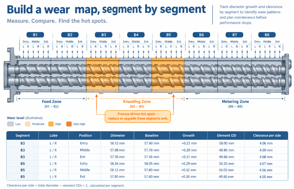
Measuring a twin screw barrel means measuring two bores that aren’t complete circles — so the single-screw method of sweeping a bore gauge around the full diameter doesn’t work. Each lobe of the figure-8 has to be measured on its own, only in directions where both ends of the gauge land on that lobe’s wall; every barrel segment has to be measured separately, because segments wear at different rates; and on counter-rotating machines the worst wear sits at a specific angle that a simple top-to-bottom reading can miss entirely. Pair those readings with element OD measurements and you have a wear map that tells you exactly which segment, which lobe, and which liner needs attention — instead of a single number that averages the problem away.
Why the Figure-8 Bore Changes the Method
A single screw barrel is one round bore: set a dial bore gauge, rotate it, read the diameter anywhere. A twin screw barrel is two overlapping bores that intersect to form one chamber — and that intersection changes what you can physically measure.
| Single screw barrel | Twin screw barrel | |
|---|---|---|
| Bore geometry | One complete circle | Two overlapping circles meeting at two cusps |
| Full diameter available | In every direction | Only in directions that stay on one lobe’s wall — any line toward the other bore exits into the intersection |
| Units to measure | One bore per barrel | Two lobes × every segment |
| Wear pattern | Concentrated in transition/compression zone | Depends on rotation direction and process layout — can be one-sided and angular |
| What else must be measured | Screw flight OD | Every element’s OD, and element position along the shaft |
| Replacement unit | Whole barrel or re-line | Individual segments or liners |
The practical consequence: a twin screw barrel wear check is a mapping exercise, not a single reading. For the general round-bore method — tools, temperature, cleaning — see our ultimate guide to extruder barrels; this guide covers what changes when the bore is a figure-8.
Tools: What Works and What Doesn’t
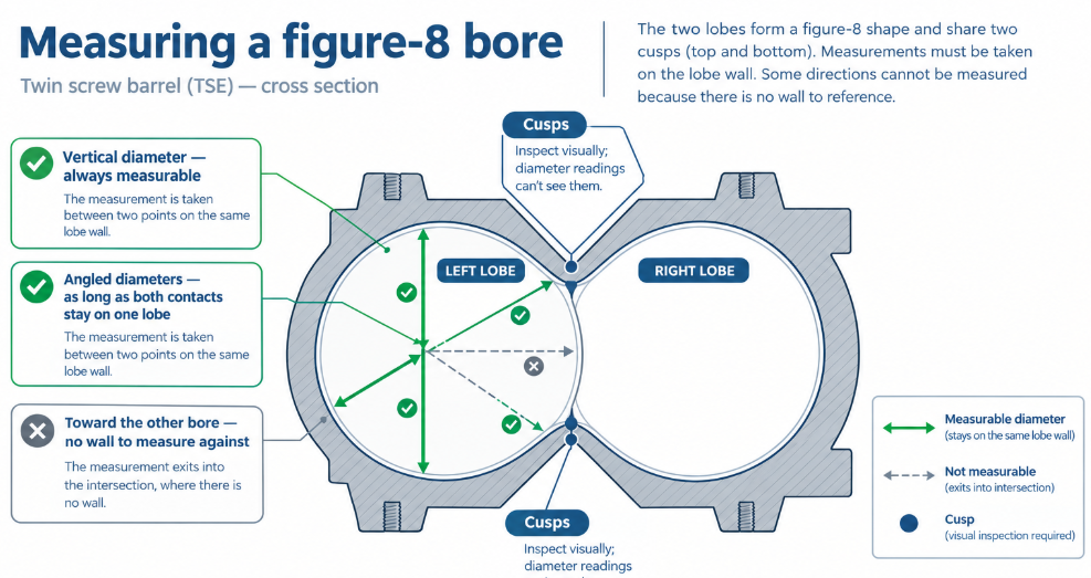
- Dial bore gauge (two-point) with an extension rod — the core tool. Set against a ring gauge or micrometer at the nominal lobe diameter, then read deviation.
- Outside micrometer — for element ODs, lobe crest by lobe crest.
- Borescope or inspection light and mirror — for the cusps, port edges, and segment joints, which diameter readings cannot assess.
- Calipers — not for bores. They can’t seat squarely in a bore or reach meaningful depth, and the error they introduce is of the same order as the wear you’re trying to detect.
- Dedicated twin-bore measuring devices exist for exactly this reason — tools built to measure the left and right bores separately along each barrel section — and on critical lines, sending the barrel to its manufacturer for a full bore scan is often faster than improvising.
Step 1: Establish the Baseline You’re Comparing Against
A wear measurement is only meaningful against a reference. In order of reliability:
- Your own as-new measurements taken when the barrel was installed — the best baseline, because it captures the actual part, not the nominal.
- The barrel drawing — nominal lobe diameter and tolerance.
- The OEM specification for your machine size.
Twin screw running clearances are set by the machine builder and vary with size, so there’s no universal number to compare against. That’s why the single most valuable habit is the one most shops skip: record the bore when it’s new. We make the same argument for single screws in our guide to bimetallic liner thickness — the bore log settles every future repair decision.
Step 2: Prepare the Barrel
- Pull the shafts and clean the bore while warm, with brass or copper tools — never steel scrapers, which score the honed surface you’re about to measure.
- Let the barrel cool to ambient temperature before measuring. Readings on a warm barrel are distorted by thermal expansion and won’t compare to anything.
- Mark lobe identity — left/right as seen from the drive end — and keep that convention permanent in your records.
Step 3: Measure Each Lobe, Each Segment
For every barrel segment, and for each lobe separately:
- Three axial positions — entry, middle, and exit of the segment. Wear is not uniform even within one segment.
- Vertical diameter — perpendicular to the plane joining the two bore centres. This diameter lies entirely on the lobe’s own wall and is always measurable.
- Angled diameters that stay on the lobe’s wall — rotate the gauge off vertical in both directions as far as it will go while both contacts remain on the same lobe.
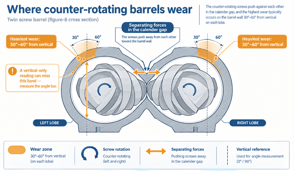
- On counter-rotating machines, include the 30°–60° band. In closely intermeshing counter-rotating extruders, large separating forces develop in the calender gap between the screws and push them toward the barrel wall, and the result is significant wear in the region defined by 30° and 60° from the vertical. A vertical-only reading can miss the worst wear on the barrel.
Then measure every segment, not a sample. Pressure and duty change along the process section, and segments under higher pressure wear faster than their neighbours — so the barrel will not age evenly, and averaging hides the one segment that needs replacing.
Where to expect the heaviest wear
| Machine / layout | Where wear concentrates | Why |
|---|---|---|
| Co-rotating compounding | Kneading zones; segments where fillers or fibers enter (side-feed and downstream) | High shear plus abrasive solids — the reason high-wear zones often get upgraded liners |
| Counter-rotating (PVC pipe/profile) | Lobe walls at 30°–60° from vertical | Calender-gap separating forces push the screws against the barrel |
| Any machine, high-pressure sections | Segments nearest the discharge and ahead of restrictive elements | Higher pressure, higher wear |
| Port edges | Feed, side-feed and vent openings | Material erosion at the edge of the cut-out — see feed barrel and vent barrel |
Step 4: Measure the Elements — and Map Them to the Barrel
Barrel wear is only half of the clearance. For every element:
- Measure the OD across each lobe crest with a micrometer. Crests wear unevenly, and a trilobal or bilobal element’s worst lobe governs.
- Record the element’s position on the shaft so its reading can be matched to the barrel segment it runs in.
- Look at the crest profile — rounding of the tip reduces the element’s wiping action even where the OD reads close to nominal.
Now combine: clearance per side = (lobe diameter − element OD) ÷ 2, calculated segment by segment. That’s the number that governs leakage and process behaviour — and it’s usually the pairing, not either part alone, that has drifted. Element fundamentals are in our twin-screw elements guide.
Step 5: Inspect What Diameter Readings Can’t See
- The cusps. The two edges where the lobes meet are thin sections of the liner. Rounding, chipping, or erosion there opens a leakage path between the two bores that no diameter reading will reveal. Inspect them visually along every segment.
- Segment joints. Steps or misalignment between adjacent segments catch material and create stagnation; worn joints show as a ridge or a lip when viewed down the bore.
- Port edges. Erosion or burrs around openings affect feeding and venting behaviour.
- Surface condition. Scoring, pitting, and corrosion — pitting on acid-generating materials means the liner material, not only the dimension, needs attention.
Step 6: Record It as a Wear Map
A simple table per inspection turns readings into decisions:
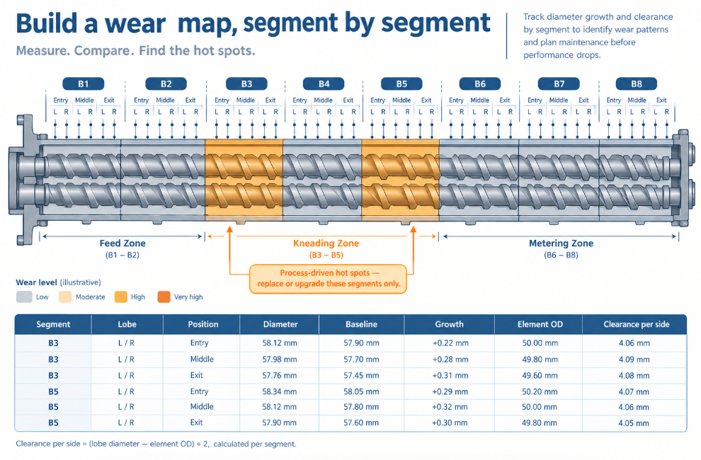
| Segment | Lobe | Position | Vertical Ø | Angled Ø (max) | Baseline Ø | Growth | Element OD | Clearance/side | Notes |
|---|---|---|---|---|---|---|---|---|---|
| B4 | L | Entry | |||||||
| B4 | L | Middle | |||||||
| B4 | R | Entry | |||||||
| … |
Kept over successive inspections, the map shows wear rate per segment — which is what lets you plan replacement before the process tells you, and upgrade only the segments that need it.
Step 7: Interpret and Decide
- Clearance near 2× as-new in a segment → that segment is at its performance limit. Run the figures through our wear limit calculator; the 2× principle applies to twin screws, with your own baseline as the as-new value.
- One segment far worse than the rest → a process-driven hot spot (filler entry, high-shear zone). Replace that segment or its liner, and upgrade its material rather than repeating the same one — the “don’t buy a whole wear-resistant barrel, upgrade the high-wear zones” logic in our twin screw barrel configuration guide.
- One lobe consistently worse than the other → look beyond wear at shaft alignment and gearbox condition; asymmetric wear has an asymmetric cause.
- Wear concentrated at 30°–60° on a counter-rotating machine → expected pattern; the rate is what matters, and rising screw speed accelerates it.
- Liner worn but casing sound → liner replacement may be the economical route; see barrel repair vs replacement for the decision logic and our liner and sleeve page for what we supply.
Symptoms That Should Trigger a Measurement
| Symptom | What it suggests |
|---|---|
| Specific mechanical energy drifting at unchanged rate and speed | Clearance opening — the earliest process signal of wear |
| Product properties drifting batch to batch, recipe unchanged | Uncontrolled shear from worn segments |
| Melt temperature rising at the same settings | Leakage and re-shearing |
| Throughput limited, rising screw speed needed | Advanced wear — measure before it gets here |
| Metal content in pellets, dark specks | Surface degradation or shedding — inspect liner surfaces |
| Performance differs after swapping elements between shafts | Asymmetric lobe wear |
A twin screw barrel wears the way it’s used — segment by segment, lobe by lobe, and on counter-rotating machines at an angle — so the only measurement worth taking is one that keeps those differences instead of averaging them: each lobe, each segment, paired with the elements that run in it, against a baseline you recorded when the barrel was new.
At BLOOM, we manufacture twin screw barrels and replaceable liners, plus twin-screw elements, built to drawing or reverse-measured from your worn parts. If you’ve mapped your barrel and want a second opinion on which segments to replace — or which to upgrade — send our engineering team your wear map, machine make and model, and what you process on WhatsApp, and we’ll tell you what the numbers say.
References and Further Reading
- The Role of Calender Gap in Barrel and Screw Wear in Counterrotating Twin Screw Extruders, Polymers (NCBI PMC) — large separating forces in the calender gap of closely intermeshing counter-rotating twin screw extruders pushing the screws toward the barrel wall, resulting in significant wear in the region between 30° and 60° from the vertical: https://www.ncbi.nlm.nih.gov/pmc/articles/PMC8037425/
- US Patent 10,036,622 (USPTO) — a barrel measuring device for twin screw extruders measuring the left and right bores separately, wear increasing bore diameter, and higher pressure in downstream barrel sections causing those sections to wear more quickly: https://image-ppubs.uspto.gov/dirsearch-public/print/downloadPdf/10036622
- US Patent 5,816,699 (USPTO) — twin screw barrel segments lined with wear- and corrosion-resistant alloys that eventually wear out and must be replaced, the difficulty of accurately machining such layers, and replaceable inserts for segmented barrels: https://image-ppubs.uspto.gov/dirsearch-public/print/downloadPdf/5816699




Pingback: Conical Twin Screw Barrel: Sizes, Wear & Specs