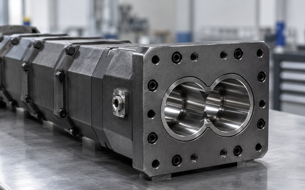
The discharge barrel is the section where a twin screw extruder stops mixing and starts pumping — and a co-rotating twin screw is a poor pump. Every bar of head pressure has to be built in the last few diameters of the barrel, and because melt leaks back over the flights at high screw speed, that pressure turns into heat. A widely used rule of thumb puts the melt temperature rise at roughly half the discharge pressure in bar: 40 bar costs about 20°C. The same pressure also loads the discharge elements and barrel bore harder than anywhere else downstream, which is why this section usually shows wear first in the pumping zone.
By the BLOOM Engineering Team
This article looks at the discharge barrel from the hardware side: what the section has to do, why pressure is expensive there, how much barrel length pressure consumes, when a gear pump changes the picture, what sits at the end of the barrel, and how to specify and inspect the section so it does not quietly cap your output.
What the Discharge Section Does
In a co-rotating twin screw extruder, most of the barrel runs partially filled. Feeders set the rate, the screws convey material forward faster than it arrives, and melting, mixing and venting all happen in channels that are only part full. The discharge section is the exception. Its job is to:
- Fill the screw channels completely so the melt can develop pressure.
- Pump steadily against the resistance of the screen pack, adapter, die or pelletizer plate.
- Do both without adding unnecessary heat to a melt that has already been mixed and devolatilized.
Co-rotating intermeshing screws are self-wiping and open from one channel to the next, which makes them excellent mixers but weak positive-displacement pumps. Counter-rotating intermeshing screws form closed C-shaped chambers that carry material forward more like a gear pump, which is one reason they are used for PVC profile and pipe. For a comparison of the two layouts, see our guide to types of twin screw extruders.
For a co-rotating compounding line, the discharge barrel is therefore a compromise zone: long enough to build the pressure the downstream equipment demands, short enough that the filled melt does not back up into the last vent, and wear-resistant enough to survive the highest pressure in the machine.
Why Pressure Is Expensive Here
Twin screw compounders often run at 300–600 rpm and above. Pressure in the discharge zone pushes melt back over the flight tips and through the intermeshing region — overflight and leakage flow. That back-flowing melt is sheared hard in the narrow tip clearance, and the shear energy becomes heat.
The practical rule is that melt temperature rises by roughly half the discharge pressure expressed in bar:
| Discharge pressure | Approx. extra melt temperature rise | Practical meaning |
|---|---|---|
| 20 bar (≈290 psi) | ~10°C | Comfortable for most commodity compounds |
| 40 bar (≈580 psi) | ~20°C | Noticeable for heat-sensitive resins and additives |
| 60 bar (≈870 psi) | ~30°C | Risk to PVC, flame retardants, PET IV, colour |
| 80 bar (≈1,160 psi) | ~40°C | Usually a sign the die or screen is the bottleneck |
The rule is directional, not exact. Screw speed, element geometry, melt viscosity and clearance all change the number. Its value is that it makes pressure visible as a cost: every restriction you add downstream — a finer screen, a smaller die land, a colder adapter — is paid for in melt temperature at the discharge barrel.
Clearance matters here as well. As the barrel bore and flight tips wear, the gap the melt leaks through grows, leakage rises, and the section needs more filled length to build the same pressure. A worn discharge barrel produces both a hotter melt and a less stable one.
The Pressure-Build Length
Pressure is built over a filled length of screw. The higher the pressure required, the longer that filled length becomes, and the further it reaches back up the barrel.
This is where the discharge barrel and the vent barrel interact. Process guidance for co-rotating machines places the last vent roughly 6 diameters from the end of the barrel for a typical compounding line feeding a pelletizer, and around 10 diameters for direct extrusion to a die, because direct extrusion needs more pressure and therefore more filled length. If the filled length grows until it reaches the vent opening, melt rises into the vent — vent flooding — and the line has to slow down or the screen and die restriction has to come down.
| Line type | Typical last-vent position from barrel end | Why |
|---|---|---|
| Compounding to strand or underwater pelletizer | ~6D | Moderate head pressure, short filled length |
| Direct extrusion to sheet, profile or film die | ~10D | Higher pressure, longer filled length |
| Any line with a melt gear pump | Can be shorter | Pump builds the pressure; screw only feeds it |
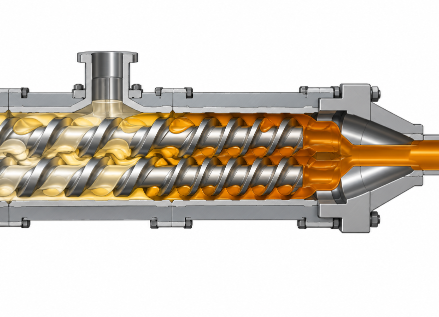
When you plan a barrel layout, treat the discharge section and the last vent as one decision. For how we position each barrel segment, see how we approach twin screw extruder barrel configuration; for what happens at the vent itself, see the twin screw vent barrel and devolatilization.
Element choice inside the discharge zone also matters. Conveying elements with a smaller pitch near the end fill more readily and pump with less leakage than large-pitch elements, at the cost of lower throughput capacity. The goal is the shortest filled length that still delivers stable pressure.
The Gear Pump Option
When the downstream process needs high, steady pressure — sheet, film, fine-filtration lines, or heat-sensitive materials — a melt gear pump between the extruder and the die changes the role of the discharge barrel completely.
| Twin screw builds the pressure | Twin screw + melt gear pump | |
|---|---|---|
| Pressure at the screw tip | Full die/screen pressure | Low, typically ~400–800 psi pump inlet |
| Pressure the pump adds | — | Differential of 4,000 psi or more is common |
| Melt temperature from pressure build | Rises with discharge pressure | Markedly lower |
| Filled length in the barrel | Long; competes with last vent | Short; vent can sit closer to the end |
| Wear on discharge elements and bore | Highest in the machine | Reduced, because the screw is no longer the pump |
| Control approach | Screw speed and feed rate | Control loop holds pump inlet pressure at setpoint |
The gear pump does not remove the discharge barrel; the screws still have to fill the pump inlet consistently. But it lets the discharge section run at a fraction of the pressure, which lowers both melt temperature and wear. The trade-off is added equipment, another heated zone and the need for reliable inlet pressure control. For how pelletizing lines balance these choices, see pelletizing line extruder screw requirements.
The Hardware at the End of the Barrel
The discharge barrel ends where the twin bore has to become a single round flow channel. That transition is short, but it causes a surprising share of quality problems.
- Figure-8 to round transition. The adapter or end flange converts the figure-8 bore into a round channel. Any step, ledge or dead corner becomes a place where melt sits, degrades and later sloughs off as black specks or gels. The transition should be streamlined, with no hold-up zones. For how hang-up points create contamination, see what causes black specks in PVC extrusion.
- Pressure and temperature ports. Melt pressure transducers and thermocouples near the discharge should sit flush with the bore wall. A recessed port is a small dead pocket; a protruding one can be struck by the screw tips.
- Adapter heating. The end flange, adapter and screen changer are thick steel sections that are easy to under-heat. A cold adapter raises viscosity, which raises pressure, which raises melt temperature at the barrel — the opposite of what an operator expects. For heater band, zoning and thermocouple placement, see extruder barrel temperature control hardware.
- Mating faces and alignment. The last barrel segment, end plate and adapter must seat squarely. A misaligned face creates a step at the joint, and at full discharge pressure even a small step leaks or hangs up material.
- Screw tip geometry. The ends of the two screws should be matched to the end-plate profile so that the volume between the screw tips and the transition is as small as practical.
What Wears First — and What That Does
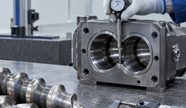
Because pressure is highest at the discharge, the elements and barrel bore in the pumping zone carry the greatest load from leakage flow. With abrasive fillers such as glass fibre, talc, calcium carbonate or flame-retardant minerals, that load becomes wear. As the clearance opens, the zone loses pumping efficiency, and the loop reinforces itself:
Bore and flight tips wear in the discharge zone
        ↓
Leakage over the flights increases
        ↓
More filled length needed to build the same pressure
        ↓
More shear, more heat, longer residence in the filled zone
        ↓
Faster wear — and eventually the filled length reaches the last vent
Three practical consequences follow for buyers and maintenance teams:
- Specify the discharge section for wear, not just the melting zone. On filled or abrasive compounds, the discharge barrel and the last conveying elements justify the same upgraded material as the kneading zone. Options include bimetallic screw and barrel construction and, for the most abrasive formulations, tungsten carbide screw and barrel linings.
- Measure the discharge section first. When you inspect a twin screw barrel, include the last barrel segment alongside the melting and side-feed sections — each lobe separately. The procedure is in how to measure twin screw barrel wear, and you can compare measured clearance against the replacement threshold with our screw wear limit calculator.
- Lower pressure where you can. A coarser screen, a correctly heated adapter, a larger die land or a gear pump all reduce the load on the discharge section. Lower pressure is the cheapest wear protection available.
Symptoms and What They Point To
| Symptom at the discharge | Likely cause in the discharge section | First check |
|---|---|---|
| Melt temperature well above barrel setpoint | High head pressure turning into shear heat | Screen pack, adapter temperature, die restriction |
| Vent flooding at normal rate | Filled length too long | Discharge pressure; wear in last barrel segment |
| Pressure surging at the die | Unstable filling of the pumping zone | Feeder stability; element pitch; clearance |
| Output dropping at the same screw speed | Worn discharge elements and bore | Measure last segment bore and element OD |
| Black specks or gels after a long run | Hang-up at figure-8-to-round transition | Adapter transition, ports, mating faces |
| Discolouration or IV loss only at high rates | Pressure-driven temperature rise | Consider lower pressure or a gear pump |
| Leakage at the end flange | Misaligned or damaged mating faces | Face condition, bolt torque, alignment |
In short, the discharge barrel is where pressure is paid for in heat and wear, so the best discharge section is the one that builds only the pressure the process truly needs — on elements and a bore that can hold their clearance.
If you are planning a new barrel layout, upgrading a discharge section for an abrasive compound, or replacing worn segments, BLOOM manufactures extruder barrels and extruder screws and screw elements to your machine’s drawings and measured dimensions. Send us your barrel diameter, compound and current discharge pressure on WhatsApp, and our engineering team will review the section with you.
References and Further Reading
- Plastics Technology. “Strategically Manage Pressure to Help Ensure Quality in Co-Rotating Twin-Screw Extrusion.” Plastics Technology. https://www.ptonline.com/articles/strategically-manage-pressure-to-help-ensure-quality-in-co-rotating-twin-screw-extrusion-
- PlasticsToday. “Direct Extrusion with Twin-Screw Extruders.” PlasticsToday. https://www.plasticstoday.com/plastics-processing/direct-extrusion-with-twin-screw-extruders
- United States Patent and Trademark Office. US Patent 10,036,622 (twin screw extruder discharge and pressure-build arrangement). https://image-ppubs.uspto.gov/dirsearch-public/print/downloadPdf/10036622
- United States Patent and Trademark Office. US Patent 9,738,025 (flange converting a figure-8 extruder bore to a round flow channel). https://image-ppubs.uspto.gov/dirsearch-public/print/downloadPdf/9738025