
We machine and rebuild screws and barrels in Zhangjiagang, and the groove feed screw barrel is the one component where the gap between what a customer expects and what they get is widest. A smooth-bore barrel is forgiving — get the compression ratio roughly right and it will run. A grooved feed barrel is not. It is a system: grooves, cooling, thermal isolation and a matched screw. Get one of the four wrong and you don’t get a slightly worse extruder, you get one that surges, plugs, or destroys its own feed section inside two years.
This guide is written from the repair bench rather than the brochure — what a groove feed screw barrel does to solids conveying, the geometry numbers published research actually supports, the four specification mistakes behind most of the drawings we send back, and the four failure modes behind most of what arrives for rebuild.
What Is a Groove Feed Screw Barrel?
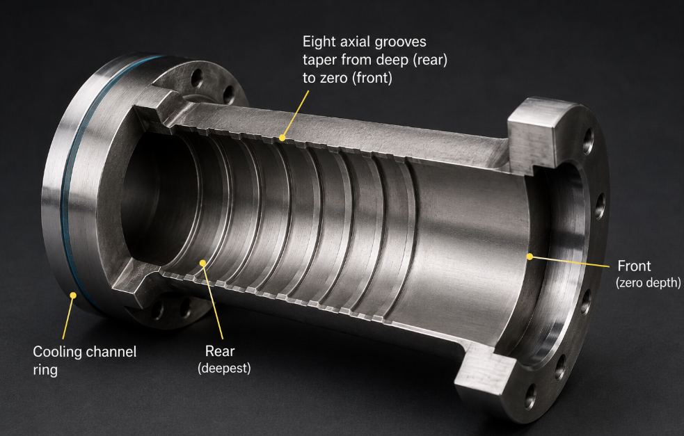
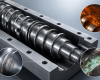
A groove feed screw barrel is a single-screw extruder barrel whose feed-section bore carries machined grooves instead of a smooth cylindrical surface. In most modern designs the grooved zone is not cut into the barrel body but into a separate, replaceable groove feed bush — also called a feed bushing, grooved liner or grooved sleeve — seated inside a water-cooled outer casing.
That construction determines your spare-parts cost for the next decade, so it is worth understanding before you buy. A classic patented feed bushing design specifies three elements: a grooved bushing, an outer casing and a cooling system. The grooved insert can be cemented carbide, metal oxide or another extremely hard, wear-resistant material, while the reinforcement around it is high-strength tough steel that withstands very high tensile stress. The press-fit shrink allowance between them is deliberately set so that even at maximum melt pressure the brittle insert stays pre-stressed in compression and cannot fracture. Cooling channels are machined into the reinforcement’s outer surface, sealed by rings ahead of and behind the channel, and a feather key stops the bushing rotating relative to the casing.
Every one of those details exists because something went wrong on somebody’s line first. Remember the feather key — a loose bush is one of the most common things we are asked to fix.
Market terminology is loose, so to be precise about what you are ordering:
- Groove feed screw barrel — the complete barrel assembly with a grooved feed section, usually supplied with its matched screw
- Groove feed bush / feed bushing / grooved liner — the replaceable grooved sleeve alone, the actual wear part
- Grooved feed section (GFS) — the zone or the design principle, not a part number
- Feed throat / feed casing — the housing under the hopper carrying the bush and cooling jacket
When a customer asks us to price a “groove feed screw barrel,” our first question is which of the four they need. About half the time it is only the bush.
How a Groove Feed Screw Barrel Changes Solids Conveying
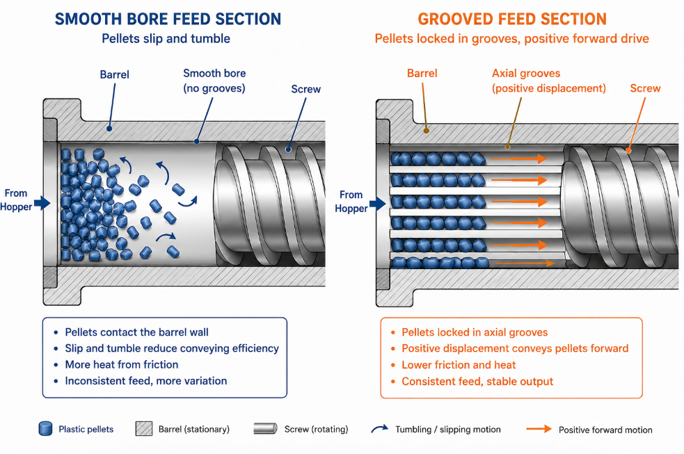
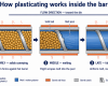
To see why a groove feed screw barrel behaves so differently, look at what moves material in a smooth-bore machine. Pellets advance through drag against the rotating barrel wall — but only the top layer actually touches the barrel, and each layer beneath moves slower because of slip between layers.
That mechanism is weak. As Jim Frankland has written in Plastics Technology, feed efficiency in a smooth-bore feed throat is typically only 15–30% of channel volume, precisely because particles slip against the wall. It is also fragile in a second way: as head pressure rises, reverse pressure flow develops in the screw channel, subtracting from output while raising melt temperature as material recirculates. That is exactly the problem in processes with inherently high head pressure — blown film, extrusion coating, thin-wall tubing.
A grooved feed barrel attacks the root cause. Grooves in the feed bore resist rotation of solid particles with the screw. Instead of shearing against a slippery wall, pellets lock into the grooves and are pushed axially — behaviour that moves away from friction drag toward positive displacement, closer to a gear pump than a friction conveyor. Frankland notes this can multiply conveying efficiency several times over.
Published performance numbers are consistent: with many polymers a grooved feed extruder produces 20–40% higher output per rpm than the same-diameter smooth-bore machine, while improving solids conveying, increasing pumping action, reducing energy input and lowering melt temperature. This is not new technology — grooved feeds debuted in Europe in the 1950s, giving European processors decades to establish where it helps and where it does not.
There is a second-order effect most suppliers never explain, and it matters more than the headline number. Because the barrel is essentially a pressure pipe, pressure developed in the grooved zone transfers down the barrel and counteracts discharge resistance. If feed-section pressure exceeds discharge pressure, output can exceed drag flow — a throughput gain stacked on top of the conveying gain. This is why a well-designed groove feed screw barrel pushes through restrictive tooling that would choke an equivalent smooth-bore machine.
Intense cooling is not optional in this arrangement. The grooved throat must be cooled hard so material does not melt prematurely and destroy pressure build-up. Once material softens in the grooves, softened solids simply turn with the screw instead of advancing, and the whole mechanism collapses.
Groove Feed Screw Barrel vs Smooth Bore: The Honest Comparison
We sell both, and we have no interest in talking a customer into a grooved barrel that will make their process worse — that barrel comes back as a warranty argument.
| Criterion | Smooth-bore barrel | Groove feed screw barrel |
|---|---|---|
| Conveying mechanism | Friction drag against barrel wall | Near positive displacement; particles locked in grooves |
| Feed efficiency | Typically 15–30% of channel volume | Multiple times higher |
| Output per rpm | Baseline | 20–40% higher with many polymers |
| Melt temperature | Higher | Lower at equivalent output |
| Sensitivity to head pressure | High — reverse flow cuts output | Low — feed pressure counteracts discharge |
| Feed-zone pressure | Modest | Can exceed 12,000 psi at end of grooved section |
| Cooling requirement | Simple throat cooling | Intensive water cooling plus thermal isolation, mandatory |
| Screw design | Conventional compression ratio | Shallow, low compression; often double-flighted |
| Suitable feedstock | Broad, including powders and regrind | Narrower — clean uniform pellets preferred |
| Soft polymers (many TPEs) | Workable | Grooves plug |
| Most regrind | Workable | Generally unsuitable — grooves plug |
| Sensitivity to pellet shape | Moderate | High |
| Feed-section wear rate | Low | High without correct material selection |
Two rows deserve emphasis, because they are where customers get hurt.
Regrind. Frankland states plainly that grooved feed is generally unsuitable for most regrind because the grooves plug — the same applies to soft polymers such as many TPEs. “We also run some regrind” is one of the most common things a customer mentions casually after the barrel has been quoted.
Pellet shape. Frankland describes a polymer supplier who had to make special pellets specifically for grooved-feed processors: customers running grooved sections were getting 20% less output from material of identical intrinsic viscosity, purely because the pellet geometry came from a different supplier. A groove feed screw barrel makes your process more productive and simultaneously more sensitive to what you feed it. If your resin supply is inconsistent, that sensitivity is a real cost.
Groove Feed Screw Barrel Geometry: The Numbers That Actually Matter
This is where the drawings we receive go wrong most often.
Groove Count and Width in a Groove Feed Screw Barrel
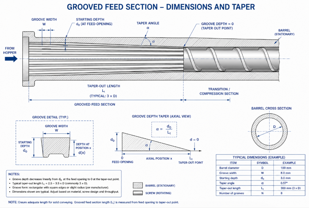
Groove count follows resin viscosity, not house style. Plastics Technology reports that a 3.5-inch extruder may carry eight to eighteen grooves evenly distributed around the feed bore, with higher-viscosity resins such as HMW-HDPE and polypropylene generally benefiting from more grooves and lower-viscosity resins needing fewer.
More is not better. Too many grooves feed resin into the mixing stage faster than the screw can melt it, producing melting inefficiency and mixing problems — an unmelt fault that gets blamed on the screw for months before anyone inspects the feed bush.
Typical groove width runs 0.15–0.3 in. (≈3.8–7.6 mm). A patented design frames it more usefully: parallel-sided grooves spaced about two resin-pellet diameters apart, with average depth roughly equal to width. Sizing the groove against the actual pellet is the right instinct, and it explains why one drawing performs differently in two plants running nominally the same resin.
Groove Depth and Taper in a Groove Feed Screw Barrel
Grooves are deepest at the rear under the feed opening and taper forward to nothing.
| Parameter | Published range | Source basis |
|---|---|---|
| Starting groove depth | 0.12–0.37 in. (≈3.0–9.4 mm) | Plastics Technology |
| Groove width | 0.15–0.3 in. (≈3.8–7.6 mm) | Plastics Technology |
| Groove width relative to pellet | ≈2 pellet diameters | US Patent 4,842,788 |
| Depth vs width at feed throat | ≈1.5 × groove width | US Patent 4,842,788 |
| Taper-out length | 3–4 D past downstream end of feed opening | Plastics Technology |
| Alternative taper-out length | 6–9 barrel diameters | US Patent 4,842,788 |
| Grooved zone length (conical grooves) | ≈3 D | US Patent 4,439,041 |
| Taper angle (experimental rig) | 0–3°, max depth to ≈5 mm | Sikora, Polymer Eng. & Sci. |
Note the disagreement on taper-out length: 3–4 D in one source, 6–9 D in another, about 3 D in the conical-groove patent. That spread is not sloppy reporting — it reflects genuinely different design philosophies for different resins and pressure targets. This is the strongest argument against copying groove geometry from another drawing: the number that is right depends on which philosophy the rest of your machine was built around.
Taper angle is a real performance lever. Sikora’s work in Polymer Engineering & Science, using a mechanism that varied taper angle continuously from 0 to 3 degrees during extrusion — a maximum groove depth from zero to nearly 5 mm — found the best results at the largest angle tested. The paper adds the qualification that matters: the significance of taper and depth depends on the design of the whole plasticating system, especially the screw, which must be adapted to the increased flow.
Axial vs Helical Grooves in a Groove Feed Screw Barrel
Most grooved feed systems use grooves parallel to the screw axis. Helical grooves are the newer alternative, developed in the 1970s to reduce deflection of groove flow in the peripheral direction.
The research case is strong: correctly designed helically grooved extruders have shown greater pumping efficiency, lower driving torque, lower cooling capacity requirements, reduced groove-edge wear and better self-cleaning. In the Helibar-type design studied at Stuttgart, the feed section carries tapered helical grooves while the melting section carries flat axial or helical grooves; because melting-zone transport improves, the feed zone is largely relieved of its pressure build-up duty, frictional heat drops, and cooling becomes far simpler.
Lower cooling demand, less groove-edge wear and better self-cleaning answer three of the four failure modes below. Helical grooves cost more to machine — that is the honest trade-off — but if your plant has a history of plugged grooves or short bush life, this is the conversation to have.
Cooling and Thermal Isolation on a Groove Feed Screw Barrel
If we could enforce one rule on groove feed screw barrel installations, it would be this one: cheapest to get right, most expensive to get wrong.
The physics is unforgiving. The grooved throat must be intensively cooled so material does not melt prematurely and undermine pressure development. When cooling is interrupted, elevated temperature softens the extrudate inside the grooves — and softened solids rotate with the screw rather than advancing axially. Output collapses, and grooves become difficult to clean once plugged or bridged.
The patent literature names two causes of that plugging: interrupted cooling and excessive back pressure. Both are operational, not manufacturing defects. That is why we are insistent about cooling capacity before shipment — we would rather argue about flow rates before the barrel ships than about warranty afterwards.
Three mandatory requirements:
Cooling water volume and temperature. The classic design puts machined cooling channels around the reinforcement with sealing rings before and after. Volume matters more than most plants assume, and scaling inside those channels degrades it silently over years. Hard water with no filtration is a slow-motion failure in progress.
Thermal isolation from barrel zone 1. The grooved section must be thermally separated from the first heated zone. Without an effective break, heat conducts backwards into the grooves and you are cooling against your own heaters.
Feed-throat temperature as a tuning variable, not a fixed setting. Frankland’s guidance applies with double force here: optimum temperature can only be found experimentally, warming gradually and watching whether output and head pressure rise. Two nominally identical extruders can prefer different throat temperatures because of differences in surface condition and heat transfer. European processors exploit this deliberately — where grooving offers no advantage for a given resin, they heat the grooves to neutralise the action, making a grooved machine nearly as versatile as a smooth-bore one.
That last point is worth reading twice if you fear a grooved feed barrel will lock you into one product family. Heating the grooves is a field-proven way to turn the effect down.
The Screw Is Half of Any Groove Feed Screw Barrel System
We refuse orders where a customer wants a groove feed screw barrel machined to spec but intends to keep their existing screw. It does not work, and we do not want the resulting phone call.
The reason is structural: in grooved-feed machines the screw feed section is cut very shallow, so total groove cross-sectional area is of a similar order of magnitude to screw channel area. Grooves and screw channel are two halves of one flow path. Change one and the balance is gone.
Compression ratio must be low. Compression happens in the grooved section, not along the screw. A conventional compression ratio behind a grooved section compresses material that is already compressed — over-pressure, torque spikes, accelerated wear.
Decompression may be required. Since pressure at the end of the grooved section can exceed 12,000 psi, over-pressurization is a genuine design constraint. Frankland describes two remedies: modify the groove design, or build a decompression section into the screw. The screw is often the better place to solve it.
Double flights become useful. Frankland’s analysis concludes that single flights work better in smooth-bore extruders while double flights work best teamed with grooved barrels. If a supplier quotes a grooved barrel without asking about flight configuration, they are quoting a tube, not a system.
Where a Groove Feed Screw Barrel Pays for Itself
| Application | Fit | Why | Main risk |
|---|---|---|---|
| HDPE / PP pipe | Excellent | High-viscosity resin, restrictive tooling, output-driven economics | Over-pressure if screw not matched |
| HDPE / LLDPE blown film | Excellent | High head pressure from narrow die gap; lower melt temp aids bubble stability | Very sensitive to pellet consistency |
| Sheet, board, profile | Good, case by case | Benefits when resin is high-viscosity or die restrictive | Frequent product changes erode the benefit |
| Compounding / recycled | Conditional — often unsuitable | Real gains only when feedstock is clean and uniform | Grooves plug with regrind, fines, soft compounds |
HDPE and PP Pipe: The Classic Groove Feed Screw Barrel Case
The textbook application and the largest share of what we ship. Fractional-melt HDPE is exactly where a smooth-bore machine struggles: high viscosity, low feed efficiency, restrictive tooling. Grooved feeds are documented to significantly improve output with low-feed-efficiency polymers, raising throughput at lower melt temperature while overcoming higher discharge pressures — the grounds on which Europe has favoured them for decades. For pipe producers, lower melt temperature is not just an energy line item: it shortens cooling length and reduces sag risk on heavy wall.
Blown Film and the Groove Feed Screw Barrel
Blown film sits on the short list of processes where smooth-bore machines suffer most, because a narrow die gap creates inherently high head pressure — and rising head pressure means reverse flow, lost output and hotter melt. A groove feed screw barrel counteracts precisely that mechanism.
The caution is pellet sensitivity. Film plants often buy resin opportunistically across suppliers, and a grooved feed section will expose the differences in a way your old machine did not.
Sheet, Board and Profile with a Groove Feed Screw Barrel
Here we ask more questions before quoting. The benefit is real when resin is high-viscosity and the die restrictive, but sheet and profile lines run wider material ranges and change products more often. If half your production is a resin that gains nothing from grooving, you have bought sensitivity you did not need. The mitigation is heated grooves — specify it up front, because retrofitting is expensive.
Recycling and Compounding: The Groove Feed Screw Barrel Gray Zone
This is where we most often talk an order down rather than up. The published position is not ambiguous: grooved feed is generally unsuitable for most regrind because the grooves plug, the same applies to soft polymers such as many TPEs, powdered polymers and additives are outside its comfort zone, and grooved sections are poor at compounding additives without extensive mixing sections.
That does not disqualify every recycling line. Clean, uniformly re-pelletised material behaves like virgin resin; densified flake with fines does not. The dividing line is whether your feedstock is pellets or merely particles. If it is the latter, pelletise upstream, control fines, and specify helical grooves for their self-cleaning behaviour.
Four Mistakes We See on Groove Feed Screw Barrel Orders
Mistake 1: A Standard Compression Screw Behind a Groove Feed Screw Barrel
The most common and most damaging. A customer upgrades to a groove feed screw barrel, keeps the existing screw, and cannot understand why torque is up, melt is hot and the feed section is wearing fast.
The screw for a grooved feed barrel is cut shallow so groove area and channel area are comparable, with compression handled by the grooves. A standard compression ratio double-compresses the material, and that pressure goes into the barrel wall, the flights and your gearbox. If your budget covers one part, buy the matched pair for one machine rather than a grooved barrel for two.
Mistake 2: Undersized Cooling on a Groove Feed Screw Barrel
Second most common, and the one most likely to stay invisible until output has already drifted down.
The field failures we see are rarely a pump that stopped. They are: cooling channels scaled up after three years of untreated water; a thermal isolation ring replaced with a plain gasket during a rebuild; a chiller sized for the old smooth-bore machine and never upgraded; feed-throat temperature “optimised” upward by an operator chasing a torque alarm.
Ask your supplier for required flow rate and inlet temperature in writing, and log outlet temperature monthly. A rising outlet temperature at constant load is the earliest warning you will get.
Mistake 3: Copying Groove Geometry From Another Groove Feed Screw Barrel Drawing
We receive drawings traced from a competitor’s part, scaled from a different diameter, or reverse-engineered from a worn bush whose original groove depth is long gone.
The published ranges above are wide precisely because the right number depends on resin viscosity, pellet size, target pressure and screw design. Groove count follows viscosity. Width tracks pellet diameter. Taper-out length varies from about 3 D to 9 D across legitimate design schools. Copying a drawing copies someone else’s answer to a question about their resin, their screw and their pressure target.
We will machine a traced drawing if a customer insists. But we ask for resin grade, pellet dimensions, screw drawing and target output first — and more often than not, the numbers change.
Mistake 4: Running Powder or Soft Compound Through a Groove Feed Screw Barrel
Usually not made at purchase. It is made eighteen months later, when the product mix changes and nobody remembers what the barrel was specified for.
Soft polymers such as many TPEs plug the grooves. Powdered polymers and additives are generally unsuitable. Most regrind plugs the grooves. The process is unstable with hard polymers such as polycarbonate. If your mix is likely to broaden, say so at quotation stage — groove heating capability or helical grooves cost a fraction of a second barrel.
What Actually Fails on a Groove Feed Screw Barrel
| Failure mode | What the operator sees | Root cause | Typical remedy |
|---|---|---|---|
| Worn grooves | Gradual output loss at same rpm; higher melt temp | Abrasive filler or hard pigment plus high groove-zone pressure | Replace bush; upgrade groove material |
| Plugged / glazed grooves | Sudden output loss; surging; torque swings | Interrupted cooling or excessive back pressure | Clean and correct cooling; consider helical grooves |
| Loose bush in housing | Intermittent surging; noise; witness marks on bush OD | Failed anti-rotation key, worn fit, degraded seals | Re-machine housing and fit; renew key and seals |
| Over-pressure damage | Barrel distortion; abnormal wear; torque alarms | Mismatched screw or wrong groove design | Correct screw geometry; add decompression |
Worn Grooves in a Groove Feed Screw Barrel
The most economically significant failure, because it is silent. Grooves do not fail suddenly; they get shallower. Output at a given rpm falls a few percent a year, the operator compensates with rpm, melt temperature creeps up, and eventually someone concludes the machine is “just old.”
The mechanism was documented decades ago: trouble-free operation of a grooved feed section is only assured when the plasticating elements there are extremely wear-resistant, because wear is driven by hard pigments and the high pressures in the grooved zone. Both factors are elevated in exactly the applications where a groove feed screw barrel is most attractive.
The diagnostic point worth knowing: if an older extruder produces less than it used to and the screw checks out dimensionally, measure groove depth before condemning anything else. It is the most under-checked wear surface on a single-screw machine, and usually the cheapest to fix.
Plugged and Glazed Grooves in a Groove Feed Screw Barrel
The sudden version. Material softens in the grooves, packs and glazes; output falls off a cliff, feeding turns erratic, and the grooves resist cleaning.
Two named causes: interrupted cooling and excessive back pressure. Diagnose in that order — check cooling flow, inlet and outlet temperature and thermal isolation before dismantling anything. Beyond cooling, control feedstock fines; if plugging is chronic, consider helical grooves.
A Loose Bush in the Groove Feed Screw Barrel Housing
Under-discussed and frequently misdiagnosed as a screw or drive problem.
The 1984 feed bushing patent already specifies the fix: the bushing is secured against rotation relative to the outer casing by at least one feather key fastened to the casing and engaging a recess in the reinforcement, with sealing rings ahead of and behind the cooling channel. When that key fails, or the fit between reinforcement and casing degrades, the bush moves minutely under load — enough to produce intermittent surging that no amount of screw-speed tuning will fix.
Two causes in practice: rebuilds where the housing bore was not re-machined before a new bush was pressed in, and thermal cycling that has relaxed a fit which was marginal when new. We measure the housing bore first on any feed-section rebuild. Fitting a new bush into a worn housing is a repair that fails twice.
Over-Pressure Damage in a Groove Feed Screw Barrel
The most expensive failure, and almost always traceable to Mistake 1. Pressure at the end of the grooved section can exceed 12,000 psi, which is why design care is required to prevent over-pressurization — through groove design or a decompression section in the screw. When the screw does not do its half of the job, that pressure loads the barrel, the flights and the thrust bearing continuously. By the time it shows as distortion or abnormal wear, you are usually replacing both screw and barrel.
Groove Feed Screw Barrel Materials: What to Specify
Material selection for the grooved zone is a different problem from the rest of the barrel, because that zone sees both high pressure and concentrated abrasion at the groove edges.
The patent literature points at the extreme end of the range: a grooved insert of cemented carbide or metal oxide, pre-stressed in compression by a high-strength steel reinforcement so the hard, brittle insert cannot fracture under maximum melt pressure — a design intended for high-molecular-weight and heavily pigmented polymers where pigment abrasion and groove-zone pressure would destroy a conventional surface.
For most orders the practical options are nitrided steel or a bimetallic lining, chosen against abrasive content and expected pressure.
【FILL — BLOOM capability data: diameter range, material options (nitrided / bimetallic / carbide insert), nitrided case depth and surface hardness, bore tolerance and straightness spec, standard lead time, stock sizes.】
Replace the Bush or the Whole Groove Feed Screw Barrel?
The commercially important consequence of replaceable-bush construction is that worn grooves rarely require a new barrel.
Replace the bush only when groove depth has worn below spec but the housing bore is in tolerance, cooling channels are clean and the key seat is sound. This is the majority of cases and by far the cheapest outcome.
Re-machine the housing and fit a new bush when the bore has worn or a previous rebuild left the fit loose. Skipping this is the most common reason a rebuilt feed section fails again inside a year.
Replace the complete grooved barrel when there is over-pressure distortion, cooling channels are scaled beyond cleaning, or bore wear elsewhere has reached its limit anyway.
Redesign rather than replace when the barrel is doing exactly what it was built to do but the product mix has changed. Refitting the same geometry to a new resin repeats the original mismatch.
How to Specify a Groove Feed Screw Barrel: What We Need From You
If a supplier quotes without asking for most of this, that tells you something.
Resin and feedstock — grade and melt index, whether fractional melt; pellet dimensions and shape (this drives groove width); filler and pigment loading and whether abrasive; regrind percentage, form and fines content; any planned change in material mix.
Machine — screw diameter and L/D; existing screw drawing, or confirmation that a matched screw is being ordered; motor power and maximum torque; feed casing dimensions and mounting; existing bush dimensions if this is a replacement.
Process — target output and screw speed; die type and expected head pressure; available cooling water flow rate and inlet temperature; whether groove heating is wanted.
Commercial — whether you need the bush, the barrel, or the matched screw-and-barrel set; original machine make and model for fit verification.
Send drawings if you have them, but send the resin and process data too, so we can tell you whether the drawing is right.
Groove Feed Screw Barrel FAQ
How much output gain does a groove feed screw barrel deliver?
Published figures put it at 20–40% higher output per rpm than an equivalent smooth-bore machine with many polymers, alongside lower melt temperature and reduced energy input. High-viscosity resins with low feed efficiency benefit most; easy-feeding resins gain least.
Can a groove feed screw barrel run regrind?
Generally not, if the regrind is flake or carries significant fines — the grooves plug. Clean, re-pelletised material with controlled fines is a different case. For a recycling line, the upstream pelletising step matters more than the barrel specification.
Do I need a new screw with a new groove feed screw barrel?
Yes. The feed section is cut very shallow so groove area and channel area are comparable; compression ratio is low because compression happens in the grooves; decompression may be needed to manage feed-zone pressure; and double-flighted feed sections work best with grooved barrels. Reusing a smooth-bore screw is the most common and most damaging mistake in this product category.
Why has my grooved feed extruder slowly lost output?
Measure groove depth first. Groove wear is gradual and driven by hard pigments and high groove-zone pressure, so it appears as slow drift rather than a fault. If the screw checks out dimensionally and cooling is functioning, worn grooves are the likely cause — and usually the cheapest to fix, since only the bush needs replacing.
Can a groove feed screw barrel be made less aggressive for easy-feeding resins?
Yes. European processors neutralise grooved-feed action by heating the grooves, making a grooved machine nearly as versatile as a smooth-bore one. Specify heating capability at order stage if your product mix is broad.
What causes a feed bush to work loose?
Failure of the anti-rotation key, a degraded fit between bushing reinforcement and outer casing, or worn seals around the cooling channel. It commonly follows a rebuild where the housing bore was not re-machined before fitting. Symptoms are intermittent surging and noise that do not respond to screw-speed adjustment.
Talk to Us Before You Buy a Groove Feed Screw Barrel
We would rather spend twenty minutes on your resin, your screw and your cooling capacity than machine a part that comes back in a year. Send us your resin grade, pellet data, screw drawing and target output, and we will tell you honestly whether a groove feed screw barrel will help — including when it won’t.
【FILL — contact block, lead time statement, drawing-submission instructions】
References
- Frankland, J. “EXTRUSION: Are Grooved-Feed Extruders Right for You?” Plastics Technology. https://www.ptonline.com/articles/extrusion-are-grooved-feed-extruders-right-for-you
- Schut, J.H. “Understanding Grooved Feed.” Plastics Technology. https://www.ptonline.com/articles/understanding-grooved-feed
- Frankland, J. “Take Proper Care in Feeding Your Extruder.” Plastics Technology. https://www.ptonline.com/articles/take-proper-care-in-feeding-your-extruder
- Sikora, R. “The effect of the feed section groove taper angle on the performance of a single-screw extruder.” Polymer Engineering & Science, 2001. https://4spepublications.onlinelibrary.wiley.com/doi/abs/10.1002/pen.10861


Pingback: Extruder Screw Design: A Complete Engineering Guide