If you run a compounding plant, and your production lines frequently handle fiber content exceeding 30%, 50%, or even higher, you are likely familiar with this scenario: the line has been running for less than three months, and output begins to mysteriously decline. The vacuum port starts to vent material (vent-up), and the final product shows severe glass fiber protrusion (floating fiber).
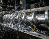
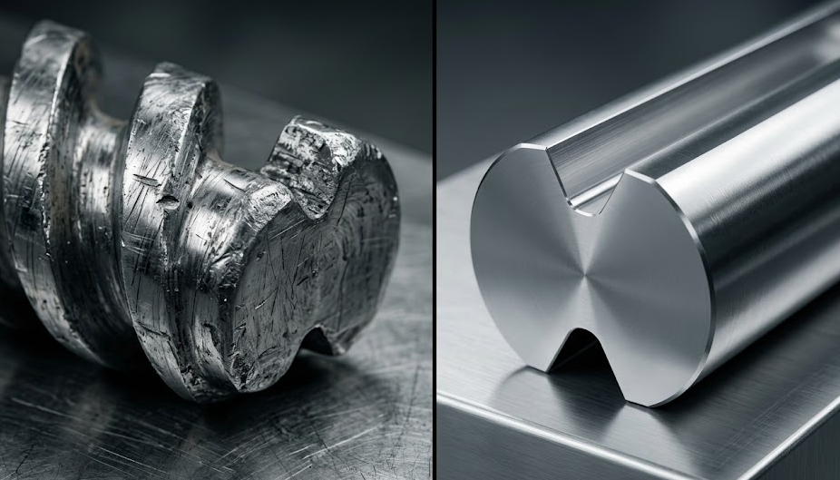
When you are forced to shut down and pull the screws, the scene is always shocking—the sharp flight edges of kneading blocks have been ground into smooth, rounded cylinders. In the worst-case scenario, accompanied by a sickening crack, the core shaft has snapped inside the barrel.
Downtime, material clearing, waiting for parts, shaft replacement… what is lost is not just a few thousand dollars in spare parts fees, but hundreds of thousands of dollars in order delivery delays and customer trust.
High-glass fiber (GF) extrusion is the “meat grinder” battlefield for extruder components. Here, there are no “one-size-fits-all” general-purpose parts; there are only precision customized solutions based on a ruthless wear logic. Today, the BLOOM Engineering Team will dismantle the anti-wear customization guide for high-glass fiber twin-screw components from three core dimensions: material science, screw configuration, and torque transmission.
1. Analyzing the Pain Point: Why Glass Fibers “Chew” Through Steel
Before diving into solutions, we must understand how the enemy attacks.
In the high-shear environment of twin-screw extrusion, glass fibers are not docile “reinforcement materials”; they are billions of microscopic “files.” When the polymer melt encapsulates these hard glass fibers, moving at high pressure and speed between the barrel wall and the screw surface, it generates two fatal forms of destruction:
- Abrasive Wear: This is direct physical cutting. The high-hardness glass fibers continuously scratch the metal surface, peeling it away like sandpaper.
- Corrosive Wear: Many engineering plastics (such as flame-retardant Nylon PA66+GF, PPS, PET, etc.) decompose at high temperatures, releasing trace amounts of acidic corrosive gases. Corrosion softens the metal surface, which is then easily scraped away by the glass fibers, forming a vicious cycle.
2. Point of Breakthrough 1: Material Down-Selection – Embracing Powder Metallurgy (PM-HIP)
In hundreds of high-glass fiber customization cases handled by the BLOOM Engineering Team, 80% of premature failures were due to “penny-pinching” in material selection. Many factories, to save initial procurement costs, continue to use conventional high-speed steel (such as W6Mo5Cr4V2) to cope with 40% glass fiber. This is like wearing a cloth shirt to stop a bullet.
To combat high wear, traditional forged or cast steels have an inherent “genetic defect”: their internal carbide particles are coarse and unevenly distributed, making them prone to microscopic spalling under the action of cutting forces.
The true ultimate weapon is: High-Vanadium Powder Metallurgy Tool Steel (PM-HIP).
The magic of the PM-HIP (Hot Isostatic Pressing) process lies in its ability to directly solidify alloy powder under high temperature and pressure, ensuring that extremely hard carbides (such as vanadium carbide) are dispersed in an extremely fine, uniform morphology within the metal matrix. This is akin to embedding billions of tiny diamonds into the steel, making it impossible for glass fibers to get a bite.
Table 1: Comparative Assessment of Core Material Performance in High-Glass Fiber Conditions
| Screw Element Material | Typical Grade Representative | Rockwell Hardness (HRC) | Internal Microstructure | High-GF Anti-Wear Life Expectancy | BLOOM Selection Advice and Economic Analysis |
| Basic High-Speed Steel (Conventional Tool Steel) | W6Mo5Cr4V2 | 58-62 | Carbide segregation, coarse particles | Approx. 2-3 months (GF>30%) | Not recommended for high-fiber. Only suitable for common unreinforced color masterbatch, PP/PE modification. The downtime cost of frequent replacement far exceeds the price difference of parts. |
| High Anti-Wear Powder Metallurgy (PM-HIP) | SAM10, CPM10V, WR15E | 60-64 | Extremely fine and uniformly dispersed carbides | Approx. 10-14 months (Lifespan increased 3-5 times) | Preferred for high-glass fiber. Although the initial procurement cost is high, it ensures stable year-round operation of the production line and has the lowest TCO (Total Cost of Ownership). |
| Bimetallic/PTA Spray Welding | Nickel-based/Tungsten Carbide Alloy | 62-65 (Surface) | Dense alloy surface layer, good matrix toughness | Approx. 8-12 months (Depends on coating thickness) | Suitable for certain composite extreme conditions requiring extremely strong anti-corrosion + wear resistance, or for large-diameter, non-co-rotating twin screws where full-size PM-HIP cannot be used. |
💼 BLOOM Real Case Study: PA66 + 45% GF Rebirth
Last year, a Turkish automotive plastic parts supplier approached us. Their production line was plagued by wear issues, using conventional high-speed steel screw elements. The kneading blocks in the melting section forced a shutdown and replacement every 45 days on average, with high scrap rates.
BLOOM Intervention: We did not change their extruder model, only replaced the kneading blocks in the high-shear region with customized CPM10V Powder Metallurgy material. The results were amazing: the production line ran continuously for 11 months under high load without significant capacity decay, and the “Overall Equipment Effectiveness (OEE)” of the equipment increased by a stunning 28%.
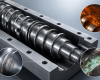
3. Point of Breakthrough 2: The Core Shaft—Heart Fatigue and Spline Customization
If screw elements are the muscles of the extruder, then the core shaft is its heart and skeleton.
The higher the glass fiber content, the greater the apparent viscosity of the melt, and the exponentially higher the torque required to output from the equipment. This is where the nightmare of many older production lines begins—shaft breakage.
Shaft breakage is usually not due to a single torque overload, but long-term Metal Fatigue and Stress Concentration. The key to whether the shaft can withstand high torque, besides the material itself (such as using high-strength alloy steel 40CrNiMoA or even aerospace-grade special steel with deep nitriding and tempering), lies in the design of the Spline Structure.
Table 2: Core Shaft Spline Evolution and Torque Bearing Capacity Comparison
| Spline Structure Type | Structural Description | Stress Distribution State | Anti-Torque/Fatigue Capacity | Application Condition Scenario |
| Traditional Single Keyway | A keyway is milled on the shaft, and torque is transmitted through a flat key | Extremely concentrated at keyway edges, prone to fatigue cracks | Weakest (obsolete edge) | Limited to early low-speed, extremely low-torque grandpa machines |
| Six-Hole/Eight-Hole Spline | Rectangular protrusions on the shaft surface, fit with the element’s inner hole | Increased area, but there’s still stress concentration at straight corner roots | Moderate | Low-to-medium torque conventional modification, low glass fiber content |
| Involute Spline | Involute gear-like mesh (such as DIN 5480 standard) | Perfect dispersion, no sharp stress concentration points, automatic self-centering | Strongest (Maximum Torque Output) | Standard configuration for modern high-torque/ultra-high torque double-screw machines, heavy-duty preferred for high-glass fiber |
BLOOM Customization Advice: If your equipment still uses six-hole splines and frequently breaks core shafts, this is not an issue that can be solved by switching to a good steel material alone. We strongly suggest re-mapping the internal space of your barrel and completely upgrading the drive system to an Involute Spline System. This is the only physical root to solving high-torque transmission bottlenecks.
4. Point of Breakthrough 3: Overlooked Arrangement—Modular Screw Combination Optimization
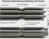
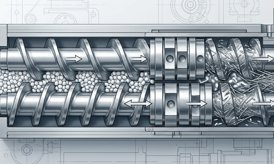
With good materials, if you don’t know “strategic deployment”, you will still die miserably. The greatest invention of co-rotating parallel twin screws is “modular screw combinations”. The BLOOM Engineering Team believes that the screw element arrangement sequence (Screw Configuration) directly determines the local force limits.
In high-glass fiber production, Kneading Blocks are often the first “suicide squad” to fall. Particularly, 90° misaligned kneading blocks have almost no axial conveying capacity, only wildly shearing the material in place, building up huge melt back pressure.
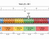
Core Rules of High-Fiber Customization Arrangement:
- Buffer Design for Side Feeder: Glass fibers are usually added through a side feeder in the middle and rear sections of the barrel. When the glass fiber just enters the barrel, it is not yet fully encapsulated by the resin, and the friction is at its maximum. Never place high-shear kneading blocks immediately after the side feeder inlet. A large-pitch conveying element (Conveying Elements) must be configured first to let the glass fiber smooth away and preliminarily mix with the melt.
- Gentle Dispersive Mixing: Use multiple sets of narrow-piece, small-misalignment (such as 30° or 45°) kneading blocks instead of single wide-piece 90° kneading blocks. By increasing the length of the mixing section, the instantaneous peak shear force is reduced, both ensuring the dispersibility of glass fibers and significantly lowering local wear.
- Cautious Use of Reverse Elements: Reverse screw elements before the exhaust port are mainly used to build pressure and create an exhaust seal. Under high-glass fiber conditions, the resistance here is extremely high, and it is extremely easy to snap the core shaft. The length and pitch of the reverse elements must be accurately calculated based on the material viscosity.
5. Details Determine Success: Unignorable Micro-Clearance
Even if you use top-tier PM-HIP powder metallurgy elements and an involute spline shaft, if the processing accuracy is not up to par, this set of expensive components is still a pile of scrap iron.
The reason why twin-screw extruders possess powerful “Self-wiping” is entirely dependent on the extremely rigorous micro-clearance control between screw and screw, and between screw and barrel.
- If the clearance is too large: The melt will produce severe “backflow” under high pressure. This not only significantly reduces output, but also leads to the material staying in the barrel for too long, causing degradation and yellowing; at the same time, local backflow will accelerate erosion and cause abnormal wear.
- If the clearance is too small: In the high-temperature, high-friction environment of high-glass fiber, metal, due to thermal expansion, easily undergoes “barrel scraping” (screws directly rubbing against the barrel’s inner wall), instantaneously scrapping the entire system.
BLOOM Engineering Team relies on high-end CNC数控机床and strict coordinate coordinate-based detection coordinates to ensure that the meshing clearance error of each set of customized elements is controlled within 0.02mm, allowing this heart to jump in its most perfect state.
System Engineering over Trial and Error
On the high-glass fiber battlefield, every blind trial-and-error burns net factory profits. Anti-wear has never been about metaphysics; it is a rigorous system engineering. It requires us to find the most perfect balance between the microstructure of powder metallurgy (PM-HIP), the physical fluid mechanics of modular combinations, and the mechanical stress of the drive shaft.
As a manufacturer focusing on the customization of extruder core components, the BLOOM Engineering Team firmly believes that the best after-sales service is not needing after-sales service. We are not just processing a piece of iron for you; we are providing you with overall solutions to extend equipment life and stabilize production line OEE.
Ready to completely solve your shaft breakage and wear troubles?Do not wait until the production line shuts down due to failure again. Send your material formulation (base resin type, GF percentage), current equipment pain points (average wear cycle, torque bottlenecks), or photos of old screws to the BLOOM engineering team. We will issue you a free dedicated High-Glass Fiber Life Upgrade and Optimization Assessment Report.