1. Why Film Screw Specification Is a Multi-Million-Dollar Engineering Decision
A polymer film extrusion line is one of the few pieces of capital equipment where the screw — a component costing 1–3% of the line’s headline price — directly determines the maximum throughput, the energy bill, and the rejection rate of the finished product for the next 10–15 years of service. Yet it remains the most commonly under-specified item in any film line RFQ.
The market context elevates the stakes. According to Business Research Insights’ 2026 market report, the global blown film extrusion machines market is projected to grow from USD 4.93 billion in 2024 to USD 6.68 billion by 2033, at a 3.4% CAGR. Cast film extrusion lines, per Verified Market Reports, are growing faster on a smaller base — USD 1.2 billion in 2024 to USD 1.8 billion by 2033 at 5.1% CAGR. The fastest-growing segment within both is multi-layer co-extrusion, where Market-Prospects projects the multi-layer co-extrusion blown film machine market to reach USD 2.5 billion by 2033, driven by a 20% rise in multilayer adoption between 2023 and 2026.
For a 5-layer blown film line built today, Davis-Standard cites typical output of 750–900 kg/hr for a 1650–1980 lbs/hr-class configuration. A 10% throughput shortfall from a poorly specified screw set, compounded over the asset’s life, is a seven-figure revenue loss. This guide breaks the screw specification into eight engineering decisions, with three reference tables to anchor RFQ conversations with suppliers.
2. Background: The Blown / Cast Process Bifurcation Drives Different Screws
Polymer films are produced by two fundamentally different routes, each imposing a fundamentally different screw architecture.
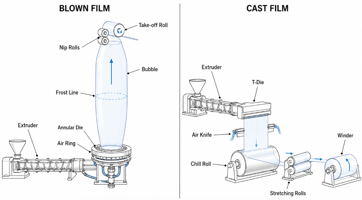
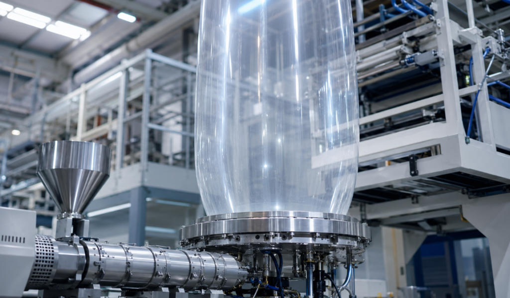
Blown film extrusion. Molten polymer is extruded through an annular die in a vertical orientation, inflated by internal air pressure into a tubular bubble, cooled externally by an air ring and optionally internally by an Internal Bubble Cooling (IBC) unit, then collapsed and wound flat. Per the ScienceDirect blown film process overview, the process needs a melt strength greater than that required by cast film processes, so lower melt temperatures are used. This single sentence dictates much of what follows in screw design: blown film screws are engineered to deliver a homogeneous melt at a controlled — and often surprisingly low — melt temperature.
Cast film extrusion. Molten polymer is extruded through a flat T-die, deposited onto a polished chill roll for rapid quenching, then drawn off in the machine direction. The ScienceDirect cast film overview documents that modern cast film screws often incorporate barrier (double-helix) sections and downstream mixing sections to handle the higher throughputs and tighter gel-count specifications the cast process demands.
The mechanical consequence is best stated as a direct output comparison. Blown film lines run typical Die Specific Output (DSO) of 0.9–4.3+ kg/cm of die circumference; cast film lines run 2.7–5.4+ kg/cm of die width. Per unit of die length, cast outproduces blown by a factor of 2–3×. This is not a marketing differentiator — it is a physical consequence of the cooling rate available to each process.
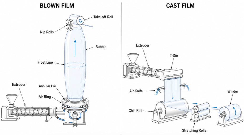
Table 1 — Blown vs Cast Process & Screw Specification Comparison
| Parameter | Blown Film | Cast Film |
|---|---|---|
| Die geometry | Annular, vertical (upward) | Flat T-die, horizontal |
| Cooling method | External air ring ± IBC | Polished chill roll (≤ 30 °C) |
| Film orientation | Biaxial (BUR + DDR) | Predominantly uniaxial MD |
| Typical film thickness | 7–100 µm | 10–150 µm |
| DSO (per unit die) | 0.9–4.3+ kg/cm | 2.7–5.4+ kg/cm |
| Melt strength requirement | High (bubble stability) | Low to moderate |
| Melt temperature window | 180–230 °C | 220–260 °C |
| Typical screw L/D | 28:1–32:1 | 30:1–36:1 |
| Typical compression ratio | 2.5–3.5 | 3.0–4.0 |
| Mixing section | Maddock, spiral common | Static + dynamic; barrier common |
| Feed system | Often grooved (HDPE/LLDPE) | Typically smooth-bore |
| Common polymers | LDPE, LLDPE, HDPE, EVA | PP (CPP), PE (CPE), barrier resins |
| Multi-layer capability | 3 to 9+ layers | 3 to 11 layers |
| Capital intensity | Lower | Higher (chill roll, gauge control) |
Sources: ScienceDirect: Blown Film overview; ScienceDirect: Cast Film Extrusion overview; Davis-Standard product literature; Verified Market Reports (2026).
The single most important consequence of this table is this: the same screw cannot serve both processes well. A buyer running a mixed product portfolio should plan for at least two purpose-built screw architectures, not one “universal” design.
3. Decision 1 — Process Type Determines Screw Architecture
Once the process is fixed, the screw architecture is largely determined.
For blown film, the canonical configuration is a moderate L/D (28:1–32:1) single-screw extruder with a gradual compression profile, a Maddock or spiral mixing section near the discharge, and — increasingly common for HDPE and LLDPE service — a grooved feed bushing for solids conveying. The grooved feed acts as a positive-displacement pump for the solids, eliminating the dependence of throughput on backpressure. Smooth-bore blown film extruders remain dominant for LDPE and EVA service, where solids conveying is easier.
For cast film, the canonical configuration is a higher L/D (30:1–36:1) single-screw extruder with a barrier section (double-helix compression zone) and an aggressive mixing section, smooth-bore feed, and the freedom to run higher melt temperatures. The barrier screw is not optional at the production scales typical of cast film service — it is the architecture that lets the line meet its rated DSO without solid bed breakup at high screw speeds.
The implication for buyers is procedural rather than philosophical: write the RFQ around process-specific screw architecture, not generic specifications. A vendor offering “one screw for both” is signaling either a limited product line or a willingness to underperform on at least one of the two services.
4. Decision 2 — The Output Gap: Why Cast Outproduces Blown by 2–3× per cm of Die
The output gap between blown and cast is the single most misunderstood number in film extrusion procurement. Buyers routinely assume that throughput can be matched by specifying a larger extruder. It cannot — at least not without secondary consequences.
The rate-limiting step in blown film is bubble cooling. The bubble is cooled by ambient or chilled air on the outside (and optionally inside via IBC), with heat transfer coefficients an order of magnitude lower than the polished chill roll used in cast film service. If the melt leaves the die faster than the bubble can be cooled to its frost-line height, the bubble destabilizes — and the line stops.
The numerical evidence is well-documented. Per the ScienceDirect blown film overview, blown film lines deliver 5–24+ lb/circumferential inch (0.9–4.3+ kg/cm) of die; cast film lines deliver 15–30+ lb/inch (2.7–5.4+ kg/cm) of die width. A typical 200 mm-class extruder feeding a 600 mm die thus delivers a sustained 50–250 kg/hr in blown film service and 160–325 kg/hr in cast service — same machine, same polymer, different cooling reality.
The procurement consequence: do not specify motor power, gearbox torque, or screw diameter as if the two processes were comparable on a kg/hr basis. Specify them against the achievable DSO for the process you are actually running. A blown film line ordered with cast film-class drive power simply burns more energy without raising output.
5. Decision 3 — Melt Temperature Window and Melt Strength Requirements
Blown and cast film impose nearly inverted requirements on melt temperature.
In blown film, the bubble must support its own weight and resist deformation between the die and the frost line. The polymer requires sufficient melt strength — a property that falls rapidly as melt temperature rises above the resin’s optimum window. For LDPE, the practical melt temperature window is 180–215 °C; for LLDPE, 200–230 °C; for HDPE, 200–230 °C; for EVA, 170–200 °C. Pushing melt temperature higher to reduce extruder amps is a common operator response that quietly degrades bubble stability and gauge uniformity.
In cast film, the polymer must spread evenly across the die’s full width and cling uniformly to the chill roll. The flatter and lower-viscosity the melt, the better the web. For PP — the dominant cast film polymer — melt temperatures of 230–260 °C are routine. For PE cast films (CPE), 220–250 °C. The screw is expected to deliver this temperature with low standard deviation (≤ ±2 °C across the melt stream); a poor screw design produces hot spots that show up as gauge defects.
The same LDPE pellet, run on a blown line and a cast line, will see a 30–40 °C delta in steady-state melt temperature. The screw’s compression ratio, mixing section, and metering depth must be designed accordingly. A screw optimized for blown film LDPE service will under-perform on cast LDPE; the reverse holds equally.
6. Decision 4 — L/D Ratio and Compression Ratio by Polymer Family
L/D ratio governs residence time and total work input; compression ratio governs the density change between feed and metering sections, which in turn governs the rate at which solid pellets melt.
The widely-cited reference value is from Lin Jin and Mark Spalding’s compression ratio study published in Plastics Technology, which concludes that an optimal screw for most LLDPE pellet resins will have a compression ratio of 2.8. Higher CR values (3.2–3.6) reduce specific rate; lower values (2.0) starve the metering section of pressure. For LDPE, the broader molecular weight distribution tolerates a wider CR window of 2.5–3.0. For HDPE, the typically pelletized resin and higher bulk density push optimal CR to 3.0–4.0. For PP, 3.0–3.5 is standard.
Table 2 — Polymer-Specific Screw Design Parameters for Film Extrusion
| Polymer | Typical L/D | Optimal CR | Recommended Mixing Section | Melt Temp (°C) | Notes |
|---|---|---|---|---|---|
| LDPE | 28:1–30:1 | 2.5–3.0 | Maddock or spiral | 180–220 | Broad MWD, easy processing |
| LLDPE | 30:1–32:1 | 2.6–2.8 | Maddock or pin mixer | 200–230 | Narrow MWD; melt-fracture risk |
| mLLDPE | 30:1–34:1 | 2.5–2.8 | Helical or dispersive | 210–235 | Narrowest MWD; high melt-fracture risk |
| HDPE | 28:1–32:1 | 3.0–4.0 | Maddock or BMC | 200–230 | Grooved feed common |
| PP homopolymer | 30:1–36:1 | 3.0–3.5 | Maddock or pin | 230–260 | CPP standard polymer |
| PP random copolymer | 30:1–36:1 | 3.0–3.5 | Maddock or pin | 220–250 | Better clarity and seal |
| EVA (≤ 18% VA) | 28:1–30:1 | 2.5–3.0 | Spiral mixer | 170–200 | Heat-sensitive; gentle screw |
| EVOH | 28:1–32:1 | 3.0–3.5 | Dispersive (low shear) | 200–220 | Barrier layer; narrow window |
| PA-6 | 30:1–34:1 | 3.5–4.0 | Maddock or BMC | 240–280 | Moisture-sensitive; dry to ≤ 0.1% |
Sources: Plastics Technology / Spalding (2025); ScienceDirect: Cast Film Extrusion; Wiley / Kazmer (2020); supplier technical literature.
Two practical rules follow from the table. First, CR is polymer-specific, not line-specific: a single screw cannot serve LDPE, LLDPE, and mLLDPE on the same extruder without compromise. Second, L/D drives the available work for mixing, not just for melting: longer L/D screws are not “better” by default — they extend residence time and can degrade heat-sensitive polymers (EVA, EVOH, PA) if not paired with proper temperature control.
7. Decision 5 — Barrier Screws and Mixing Sections: The 20% Throughput Lever
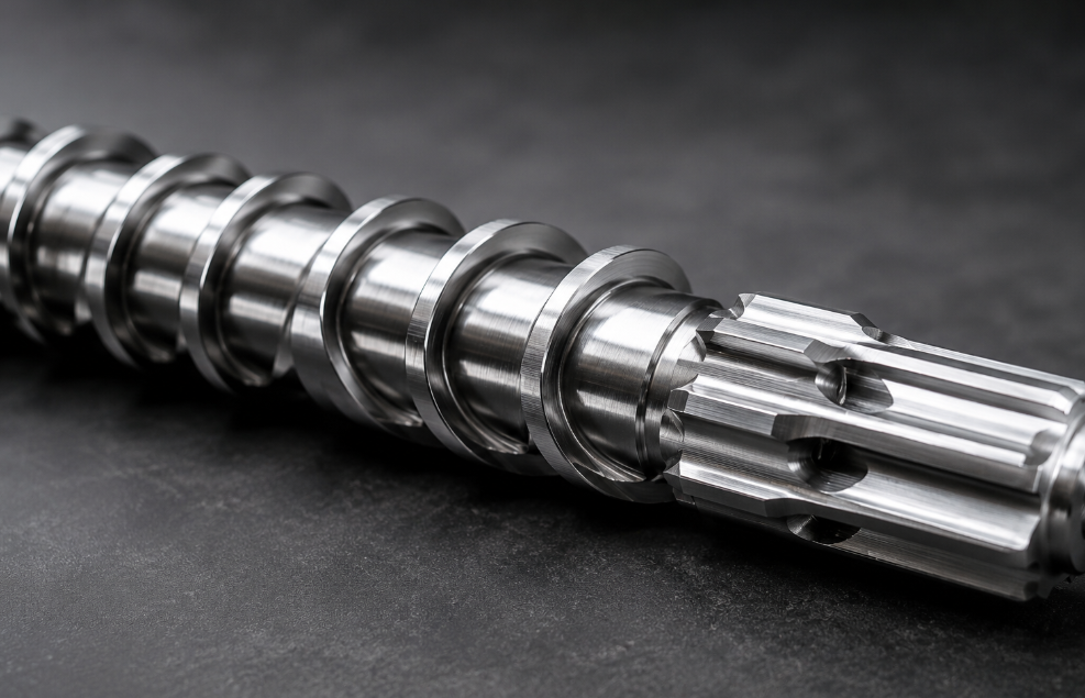
The single highest-ROI screw upgrade for film extrusion is the conversion of a conventional single-channel screw to a barrier screw with downstream mixing. The barrier section separates the solid bed from the melt pool, allowing each to be conveyed at its native efficiency; the downstream mixing section homogenizes melt temperature and disperses additives.
The case evidence is concrete. Xaloy published a converter case in which a 220 mm 30:1 single-flighted screw with mixer, processing PP with 20% calcium carbonate and 15–35% color concentrate, was replaced with an Xaloy® Efficient™ barrier screw plus helical mixer. The reported result: throughput increased by 20%, going from 750 kg/hr to 900 kg/hr — at unchanged drive power and improved melt uniformity. This is a representative number; production converters report 15–25% gains as routine for properly engineered upgrades.
Not all barrier screws are equal. Per Kazmer’s 2020 design and evaluation of barrier screws published in Polymer Engineering & Science, aggressive barrier sections can introduce excessive shear heating at higher screw speeds. The buyer’s specification should include not just “barrier screw” but the specific barrier geometry (e.g., Maillefer, Barr, Kim, or supplier-specific), the barrier flight clearance, and the downstream mixer type.
Mixing section selection follows polymer and application:
- Maddock (Union Carbide) mixers — proven dispersive mixing for general-purpose PE and PP service. Standard default.
- Spiral / helical mixers — distributive mixing without aggressive shear; appropriate for heat-sensitive polymers (EVA, EVOH).
- Pin mixers — distributive only; gentle, used for additive blending without polymer degradation.
- Pineapple mixers — combination dispersive/distributive; common in masterbatch and filled-system service.
- BMC (multi-channel) — high-end dispersive; used where gel reduction is the dominant requirement.
Specify the mixing section explicitly. “Standard mixer” in an RFQ is a procurement risk.
8. Decision 6 — The LDPE → LLDPE Driver Trap
The most common — and most expensive — screw mis-specification in blown film is the assumption that an existing LDPE screw can process LLDPE or mLLDPE with adjustments to set points. It cannot. As documented in the foundational US Patent 4,733,970, LDPE screws used for LLDPE extrusion require more torque and power than is available from most LDPE blown film extruder drives. The mismatch is structural, not procedural.
The mechanism: LLDPE has narrower molecular weight distribution and lower shear-thinning index than LDPE. At the same screw speed, LLDPE generates 30–50% higher melt viscosity in the metering section, which translates directly into 30–50% higher motor torque demand. Older LDPE-era extruder drives — typically sized for 2–3 kW/(kg/hr) — hit amp limits and trip before reaching their nameplate throughput.
The same patent warns of a secondary consequence: when LDPE drives are regeared or upgraded to handle LLDPE torque, melt temperatures rise far above the desired film blowing window. The bubble destabilizes; gauge variation increases; production rate falls below what the original LDPE line achieved.
The correct procurement response for any LDPE-to-LLDPE (or LDPE-to-mLLDPE) conversion has three components:
- New screw geometry with reduced CR (target 2.6–2.8) and increased L/D (target ≥ 30:1).
- Drive system audit: confirm the existing motor and gearbox can deliver the LLDPE torque envelope at the target throughput; budget for upgrade if not.
- Cooling capacity audit: a higher-torque screw delivers more mechanical work to the melt; barrel cooling and IBC must compensate to hold melt temperature in the 200–230 °C window.
Lines that skip steps 2 and 3 typically achieve only 60–70% of their target throughput on LLDPE — and discover the gap after the new screw is installed.
9. Decision 7 — Multi-Layer Co-Extrusion Screw Configuration
Multi-layer co-extrusion is the largest-growing segment of film extrusion. Market-Prospects notes that 4.8 million metric tons of blown film were produced globally in 2023, with a projected 20% rise in multilayer film technology adoption by 2026. Each layer of a multi-layer structure must be specified independently — both the polymer and the screw geometry that delivers it.
The functional logic of a multi-layer structure follows from packaging requirements. The outer skin layers provide printability, slip, or seal initiation; the sub-skin or tie layers bond chemically dissimilar layers (e.g., polyolefin to EVOH); the core or barrier layer delivers the package’s performance property — moisture barrier, oxygen barrier, mechanical strength, or downgauge-enabling stiffness. Each layer flows through its own dedicated extruder with its own screw and motor.
A representative configuration is Davis-Standard’s 5-layer system at 75 / 90 / 130 / 90 / 75 mm with a nominal 10 / 20 / 40 / 20 / 10 layer distribution. The largest screw delivers the highest volume (the core or barrier); the smallest screws handle the low-volume skin layers. Trying to use five identical extruders is an expensive way to under-utilize most of them.
Table 3 — Multi-Layer Co-Extrusion Screw Configuration Reference
| Layer Count | Typical Screw Diameters (mm) | Typical Layer Ratio (%) | Layer Roles | Common Polymer Set |
|---|---|---|---|---|
| 3-Layer symmetric | 65 / 90 / 65 | 20 / 60 / 20 | Skin / Core / Skin | LLDPE / LDPE / LLDPE |
| 3-Layer asymmetric | 65 / 90 / 65 | 15 / 70 / 15 | Slip skin / Core / Seal skin | mLLDPE / LDPE / EVA |
| 5-Layer A/B/C/B/A | 75 / 90 / 130 / 90 / 75 | 10 / 20 / 40 / 20 / 10 | Skin / Tie / Barrier / Tie / Skin | LLDPE / Tie / EVOH / Tie / LLDPE |
| 5-Layer simple | 90 / 90 / 120 / 90 / 90 | 15 / 20 / 30 / 20 / 15 | Skin / Sub / Core / Sub / Skin | LDPE / LLDPE / LDPE / LLDPE / LDPE |
| 7-Layer barrier | 65 / 75 / 90 / 120 / 90 / 75 / 65 | 8 / 12 / 15 / 30 / 15 / 12 / 8 | Skin / Tie / Sub / Barrier / Sub / Tie / Skin | mLLDPE / Tie / PA / EVOH / PA / Tie / mLLDPE |
| 9-Layer premium | varied | varied | Multi-barrier, ultra-thin layers | High-end food / medical / pharma |
Sources: Davis-Standard converting systems documentation; Market-Prospects multi-layer co-extrusion market analysis; supplier technical literature.
Three rules govern multi-layer screw specification:
- Each screw is selected for its polymer, not for the line. A 5-layer line is five distinct screw specifications, not five copies of one design.
- Skin layer screws are small, but not “miniature.” A skin layer at 10% of total throughput on a 600 kg/hr line still requires 60 kg/hr from a 65–75 mm screw — meaningful capacity in its own right.
- The barrier or core screw drives the line’s economics. Get the core right; the skin layers will accommodate.
10. Decision 8 — 5-Year Total Cost of Ownership: Imported vs China-Sourced
A defensible film line procurement decision requires a 5-year TCO view including capex, spare screws, energy, downtime, and qualification-cycle risk.
Reference basis for the table below: a 5-layer blown film line, 1500 mm web, 75/90/130/90/75 mm screw set, target 600 kg/hr of LLDPE/LDPE/EVOH/LDPE/LLDPE structure. USD figures, 2026, rounded for planning purposes only.
| Cost Item (5-year basis) | Imported (Reifenhäuser / W&H / Davis-Standard class) | China-Made (Premium Tier) | Notes |
|---|---|---|---|
| Initial line (extruders + dies + winder) | $2.2 – 3.2 M | $0.9 – 1.6 M | Five-layer, full automation |
| Custom screw set (5 screws) | $80 – 140 K | $30 – 60 K | PM tool steel or bimetallic |
| Installation + commissioning | $120 – 200 K | $60 – 110 K | Travel, on-site service hours |
| Spare screws & barriers (5 yr) | $120 – 200 K | $50 – 90 K | One full replacement set |
| Energy, 5 yr @ $0.08/kWh, 7000 hr/yr | $480 – 560 K | $540 – 620 K | Imported typically 8–12% more efficient |
| Unplanned downtime cost | $40 – 80 K | $120 – 240 K | Parts lead-time, support response |
| Qualification-cycle risk premium | Low (priced in) | Medium | First-year converter rejections more likely |
| 5-Year TCO Range | $3.1 – 4.4 M | $1.8 – 2.7 M | Imported is ~1.6–1.8× higher |
The capex math is unambiguous; the qualification-risk math is less so. For high-end food and pharmaceutical multi-layer films where every roll is FDA-audited downstream, imported equipment usually wins on a risk-adjusted basis for the first reference line. For agricultural film, shrink wrap, and general industrial bags, premium China-made equipment is increasingly defensible from line one. A common pattern for serious entrants: one imported reference line, then China-sourced expansion lines once the local supplier’s metallurgy and configuration discipline have been audited against the reference.
11. Procurement Checklist: 8 Questions to Ask Every Bidder
Distill the eight decisions above into eight RFQ-ready specification questions:
- Process scope. Blown, cast, or both? If both, specify two separate screw architectures.
- Polymer range. Quote the polymer family for each extruder, including MFI / MFR range and additive load.
- L/D and CR. State L/D and CR for each screw; justify against polymer and process.
- Barrier and mixing geometry. Specify barrier type (Maillefer, Barr, Kim, etc.) and downstream mixer (Maddock, helical, pin, BMC).
- Drive sizing. Confirm motor power and gearbox torque against the worst-case polymer (typically mLLDPE or HDPE at maximum throughput).
- Multi-layer configuration. For each layer, state screw diameter, polymer, target output, and layer ratio.
- Materials and surface treatment. Specify screw material (38CrMoAlA nitrided, bimetallic, or PM tool steel) and barrel lining. (For background, see our extruder screw material comparison guide.)
- TCO commitment. Provide rated energy consumption, a five-year spare-parts price book, expected screw life in operating hours, and named in-region service support.
Every line item is verifiable in writing. The bidder unwilling to commit to one or more of them is providing useful information for the buyer’s decision.
12. FAQ — High-Frequency Procurement Questions
Q1. Can an existing LDPE blown film line be converted to handle LLDPE or mLLDPE? Sometimes — but never by swapping the screw alone. A full conversion requires (a) new screw geometry with CR reduced to 2.6–2.8 and L/D extended to ≥ 30:1, (b) drive system audit (motor amps and gearbox torque against LLDPE viscosity), and (c) cooling capacity audit to keep melt temperature in the 200–230 °C window. Conversions that skip the drive and cooling audits typically achieve 60–70% of target throughput.
Q2. What is a realistic lead time for a 5-layer blown film line and its screw set? For imported equipment (Reifenhäuser, W&H, Davis-Standard, Macchi, SML), 9–14 months for the line and 14–20 weeks for replacement screws. For premium Chinese suppliers, 6–10 months for a full line and 8–14 weeks for screws. Custom screw geometry (barrier + custom mixer) adds 4–8 weeks to either lead time.
Q3. How often must screws and barrels be replaced in routine blown and cast film service? For unfilled commodity LDPE, LLDPE, and PP service, properly nitrided screws typically achieve 25,000–40,000 operating hours before measurable flight-wear triggers replacement. For filled service (CaCO₃, TiO₂, color concentrates above 5%), bimetallic screws are mandatory and life drops to 12,000–25,000 hours. Barrel life is usually 2× the screw life. Recycled-content lines accelerate wear and should be re-evaluated annually.
Q4. Is a barrier-screw upgrade economically justified for our line? For throughputs above 200 kg/hr on a single extruder, almost always — the Xaloy case of a 20% throughput gain at unchanged drive power is representative. Payback is typically 6–18 months on the screw cost alone, before counting energy savings. For throughputs below 100 kg/hr, the gain is marginal; stay with a properly specified general-purpose screw.
Q5. Can a 3-layer line be retrofitted to 5-layer, or is a new build required? Retrofitting is possible if (a) the die can be replaced or modified to a 5-layer spiral mandrel, (b) the line frame has space for two additional extruders and feedblock connections, and (c) the original control system supports two more temperature zones and gravimetric feed loops. Most 3-layer lines built since 2015 satisfy (b) and (c); the die is the gating cost, typically 25–40% of a new-line price. For lines built before 2010, new build is usually more economic than retrofit.
13. From Specification to Predictable Throughput
A polymer film extrusion line is a 10–15-year capital asset whose throughput, energy cost, and reject rate are largely set on the day its screws are specified. The eight engineering decisions above — process choice, output gap, melt temperature window, polymer-specific L/D and CR, barrier-and-mixing configuration, LDPE/LLDPE compatibility, multi-layer layout, and 5-year TCO — are not preferences. They are the boundary conditions inside which the line either meets its rated DSO and gauge specification, or does not.
For producers entering multi-layer high-barrier film service, the practical procurement sequence is: anchor an imported reference line first, audit the metallurgy and configuration discipline of two or three premium Chinese suppliers against that reference, and only then commit subsequent expansion lines to local supply. The capex saving is real, but so is the throughput risk — and only one of those appears on the purchase order.
Sources & Further Reading
Market & industry data
- Business Research Insights. Blown Film Extrusion Machines Market — Size & Growth 2024–2033. USD 4.93 B → 6.68 B at 3.4% CAGR. https://www.businessresearchinsights.com/market-reports/blown-film-extrusion-machines-market-111562
- Verified Market Reports. Cast Film Extrusion Line Market — Size & Forecast 2024–2033. USD 1.2 B → 1.8 B at 5.1% CAGR. https://www.verifiedmarketreports.com/product/cast-film-extrusion-line-market/
- Market-Prospects. Multi-Layer Co-Extrusion Blown Film Machines in 2026: Technology Evolution, Market Drivers. Multilayer adoption +20% by 2026; market projected to USD 2.5 B by 2033. https://www.market-prospects.com/articles/multi-layer-co-extrusion-blown-film-machine-market-2026
Equipment & technology references 4. Davis-Standard. Blown Film Extrusion Machinery — 5-Layer Configuration Reference. 75/90/130/90/75 mm config and 750–900 kg/hr typical output. https://davis-standard.com/converting_system/blown-film/ 5. ScienceDirect (Elsevier). Blown Film — Process Overview. Die specific output rates and melt-strength requirements. https://www.sciencedirect.com/topics/engineering/blown-film 6. ScienceDirect (Elsevier). Cast Film Extrusion — Process Overview. Barrier and mixing screw architecture for cast service. https://www.sciencedirect.com/topics/engineering/cast-film-extrusion 7. Xaloy / Nordson. Maximizing Blown Film Throughput by Improving Melt Quality. Case study: 750 → 900 kg/hr with Efficient™ barrier screw and helical mixer. https://xaloy.com/maximizing-blown-film-throughput-by-improving-melt-quality/
Peer-reviewed and technical literature 8. Jin, L. & Spalding, M. A. How Compression Ratio Impacts Extruder Performance. Plastics Technology, 2025. Optimal CR ≈ 2.8 for LLDPE pellet resins. https://www.ptonline.com/articles/how-compression-ratio-impacts-extruder-performance 9. Kazmer, D. O. Design and Evaluation of General-Purpose, Barrier, and Multichannel Plasticating Extrusion Screws. Polymer Engineering & Science, 2020. Barrier screw shear-heating limits. https://4spepublications.onlinelibrary.wiley.com/doi/full/10.1002/pen.25333 10. United States Patent 4,733,970. Extruder Screw. Foundational documentation of LDPE-to-LLDPE driver mismatch. https://image-ppubs.uspto.gov/dirsearch-public/print/downloadPdf/4733970
BLOOM manufactures custom screws, barrels, and screw elements for single-screw and twin-screw extruders, including purpose-built configurations for blown film, cast film, and multi-layer co-extrusion service. For a technical discussion of any specification point in this guide, contact our engineering team.