Walk into a plastics plant for the first time and ask any new technician how the extruder turns pellets into molten polymer. Nine times out of ten the answer is: “the heater bands melt it.” It is an intuitive explanation. It is also wrong — at least once the machine is running at steady state.
In a properly tuned single-screw extruder running at production speed, most of the energy that melts the polymer comes from mechanical shear — the screw dragging the material against the barrel wall — not from the heater bands wrapped around the barrel. The heaters do the heavy lifting during startup, but once the system reaches equilibrium they often spend more time cooling than heating. Jim Frankland, writing for Plastics Technology, puts it bluntly: the compression ratio is set “not just to feed enough solid polymer to fill the screw, but also to introduce enough shear heating in the screw to complete melting.”
This single misconception is enough to keep a new technician confused about half of what is happening on the line. The cleanest fix is to stop thinking about the extruder as a heated tube and start thinking about it as six stages the polymer flows through. Follow the material, not the temperature dial.
The Big Picture: How an Extruder Is Organized
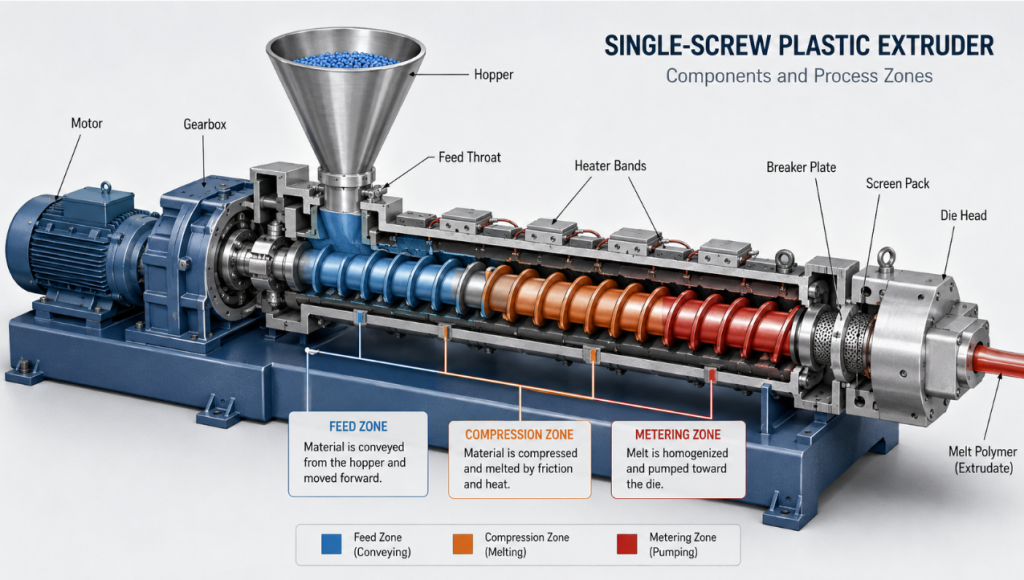
At its core, every single-screw extruder has four subsystems: the extrusion system (barrel and screw), the drive train (motor, gearbox, thrust bearing), the heating and cooling system (barrel heater bands plus cooling fans or water jackets), and the downstream equipment that takes over once the melt exits the die (calibration, cooling tank, take-off, cutting).
Most of the action happens inside the barrel, where the rotating screw does three different jobs along its length. These are usually drawn as three “zones”: feed, compression, and metering. A critical point new operators miss: these zones are defined by function, not by visible boundaries. The screw looks like one continuous helix from the outside; what changes along its length is the depth of the screw channel and, sometimes, the pitch. The transitions are gradual, and the actual location where each function dominates shifts with material, screw speed, and back pressure.
Follow the polymer through six checkpoints and the rest of the operating logic falls into place.
Table 1 — The Six Stages at a Glance
| # | Stage | Function | Dominant Force | Typical Failure Mode |
|---|---|---|---|---|
| 1 | Hopper & Feed Throat | Convey solid pellets into screw | Gravity + drag | Bridging, moisture contamination |
| 2 | Compression Section | Melt polymer via shear + conducted heat | Shear (primary) + heat | Unmelted gels, thermal degradation |
| 3 | Metering Section | Homogenize and pump melt at constant rate | Pressure | Surging, output pulsation |
| 4 | Screen Pack & Breaker Plate | Filter contaminants, build back pressure | Pressure drop | Clogged screens, pressure drift |
| 5 | Die Head & Die | Shape the profile | Shear in die channels + heat | Sharkskin, melt fracture |
| 6 | Die Swell | Elastic recovery after die exit | Viscoelastic recovery | Oversized profile, distortion |
For a 6-minute animated overview before reading on, see Paulson Training’s Extruder Operation and Control on YouTube — the Paulson series has been the de-facto operator training reference in the U.S. plastics industry since the early 1980s.
Stage 1: The Hopper and Feed Throat
The journey starts at the hopper, the funnel-shaped reservoir feeding the barrel inlet. Two things matter here, neither of them obvious.
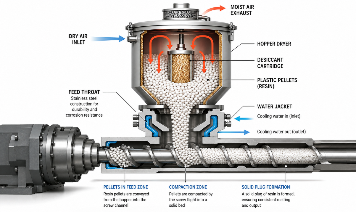
Moisture removal. Hygroscopic resins — PA (nylon), PC, ABS, PMMA — absorb atmospheric water in storage. Even fractions of a percent residual moisture will vaporize inside the barrel, leaving voids, splay marks, or hydrolytic degradation in the final product. PA6 typically needs to be dried below 0.1% moisture; PC below 0.02%. Non-hygroscopic resins like PE and PP can usually skip the dryer, but contamination from packaging fines still requires sieving.
Bite at the feed throat. Once pellets drop into the feed throat, the screw has to grab them and pull them forward. The feed throat is water-cooled on most production machines for a counterintuitive reason: if the throat gets too hot, pellets soften on the wall, stick, and bridge — forming an arch that starves the screw downstream. Operators sometimes blame surging on screw design when the real cause is a feed throat running 10 °C too hot.
In the first few diameters of the screw — the feed zone — pellets travel forward as a solid plug, not as loose particles. By the time pellets pass the third or fourth screw flight, friction and compaction have already locked them into a coherent solid mass moving forward like a slug.
💡 Real case — PA66 splay marks A nylon (PA66) extrusion line for automotive cable ties developed irregular silver streaks (splay marks) on the product surface within an hour of dryer maintenance. Operators initially chased the defect through barrel temperatures and screw speed — no improvement. The actual cause: a clogged desiccant filter had let PA66 moisture content drift from 0.04% to roughly 0.15%. After the desiccant was replaced and the resin re-dried for 4 hours at 80 °C, the surface defect disappeared. Lesson: when surface defects appear suddenly on a previously stable line running a hygroscopic resin, suspect the dryer first.
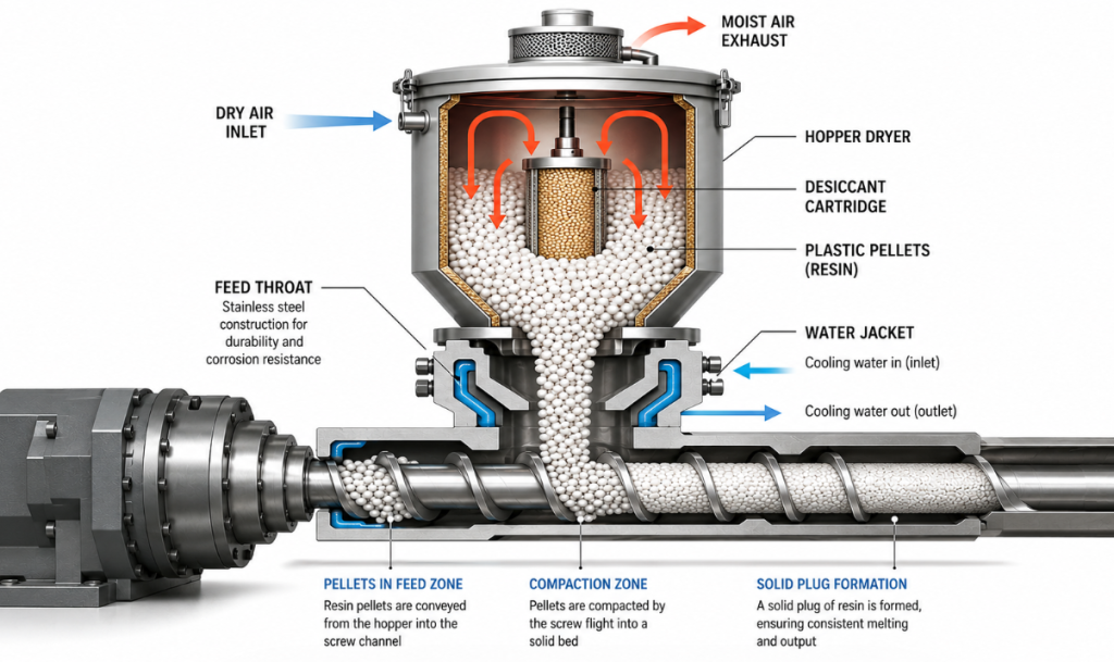
Table 2 — Drying Requirements and Melt Temperatures by Resin
| Resin | Drying Required | Drying Temp | Drying Time | Max Moisture | Typical Melt Temp |
|---|---|---|---|---|---|
| HDPE / LDPE | No (preferred) | — | — | 0.05% | 180–230 °C |
| PP | No (preferred) | — | — | 0.05% | 190–240 °C |
| Rigid PVC | Optional | 60–70 °C | 1–2 hr | 0.08% | 160–200 °C |
| ABS | Yes | 80–85 °C | 2–4 hr | 0.05% | 200–260 °C |
| PA6 / PA66 | Yes | 80 °C | 4–6 hr | 0.10% | 240–280 °C |
| PC | Yes | 120 °C | 3–4 hr | 0.02% | 260–310 °C |
| PMMA | Yes | 75–85 °C | 3–4 hr | 0.04% | 220–260 °C |
Source: aggregated from resin supplier processing guides (Covestro, Sabic, BASF, Chimei).
Stage 2: The Compression Section — Where Melting Actually Happens
The polymer reaches the compression section still as a packed solid. This is where it actually becomes a melt, and this is the stage worth understanding in detail.
The screw channel depth gradually decreases here — often by a factor of 3, giving the common 3:1 compression ratio quoted on spec sheets. As the channel volume shrinks, three things happen at once:
- Residual air trapped between pellets is pushed back toward the hopper and vented out.
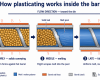
- The solid bed is pressed against the hotter barrel wall, melting a thin film at the interface.
- The screw rotation drags that melt film, generating intense viscous shear inside the polymer itself.
This last point is the one most new technicians get wrong. In a properly running line, viscous shear inside the polymer generates more heat than the barrel heaters do. Operators who watch the heater band controllers closely will notice something strange: in zones 2 and 3, the heaters are often off, and zone temperatures are maintained by the cooling fans cutting in to remove excess heat. The heater bands are essentially a startup tool and a temperature regulator, not the primary melting source. A 2020 peer-reviewed study in Polymer Engineering & Science instrumented general-purpose, barrier, and multichannel screws and confirmed that the compression ratio’s primary job is sustaining shear-driven melting, not feeding.
There is a practical consequence. Push the screw RPM up to chase higher output, and shear heating climbs faster than throughput. New operators sometimes run into thermal degradation — yellowing, char specks, gel particles — not because the heaters are too hot but because the screw is spinning too fast for the cooling system to keep up.
The compression section also determines whether the melt is homogeneous. Imperfect melting here shows up downstream as unmelted gel particles, surface roughness, or weld lines on profile products. If output quality degrades when you push speed, the compression section is almost always where to start the diagnosis.
For semi-crystalline polymers like polyethylene, the compression section typically occupies 45–50% of total screw length — almost half the working surface dedicated to one job.
💡 Real case — HDPE pipe degradation from RPM push A 110 mm HDPE pipe line increased screw RPM from 75 to 95 to meet a surge in orders. Output rose by 22%, but within four hours the line started producing pipes with brown specks and noticeable yellowing on the inner wall. Barrel zone setpoints had not changed; what did change was the actual melt temperature, which climbed from 215 °C to 248 °C purely from additional shear heating. Bringing RPM back to 80 and adding a barrel cooling-fan stage solved it. Lesson: throughput is not free — above a certain RPM, you trade product quality for output.
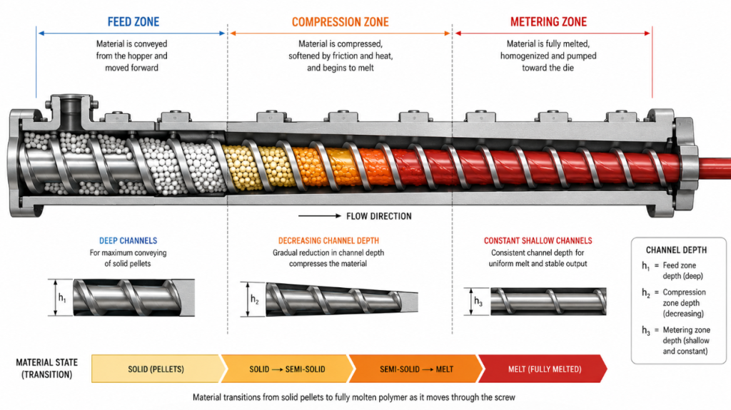
Table 3 — Compression Ratio and L/D Ratio by Polymer
| Polymer | Compression Ratio | L/D Ratio | Notes |
|---|---|---|---|
| LDPE | 2.5–3.0 : 1 | 24–30 : 1 | Standard general-purpose screw works well |
| HDPE | 3.0–4.0 : 1 | 24–30 : 1 | Higher CR for better melt mixing |
| PP | 2.5–3.5 : 1 | 24–30 : 1 | Sensitive to thermal degradation at high RPM |
| Rigid PVC | 2.0–2.5 : 1 | 20–24 : 1 | Lower CR to avoid heat-driven degradation |
| Flexible PVC | 3.0–3.5 : 1 | 24–28 : 1 | Plasticizer-rich; more shear tolerable |
| PS / HIPS | 2.5–3.0 : 1 | 24–28 : 1 | Standard, similar to LDPE |
| PC | 2.0–2.5 : 1 | 24–28 : 1 | Heat-sensitive; conservative CR |
| PA6 / PA66 | 3.5–4.5 : 1 | 22–26 : 1 | Sharp melting transition needs higher CR |
Compression ratio = h1 (feed channel depth) ÷ h2 (metering channel depth). Source: Frankland (Plastics Technology), Albis Polyolefin Sheet Extrusion Guide.
Stage 3: The Metering Section — A Built-in Gear Pump
By the time the polymer enters the metering section, melting is essentially complete. The screw channel depth is now shallow and constant. This section has one job: deliver a fully molten polymer to the die at constant temperature, constant pressure, and constant volumetric flow rate.
Think of it as a built-in gear pump. The metering section’s pressure-flow characteristic, combined with the die’s flow resistance, sets the operating point of the entire line.
Two real-world signals worth knowing:
- Surging (rhythmic output pulsation, visible as wall-thickness variation on pipe or weight variation on cut parts) usually traces back here. A common cause is upstream: incomplete melting in the compression section means alternating melt-rich and solid-rich material reaching the metering zone, which cannot smooth it out fast enough.
- Pressure at the screen pack is the single best diagnostic for metering health. A stable line should hold barrel-head pressure within ±2% over minutes. Drift or oscillation beyond that range is the first sign that something upstream — feeding, melting, or screw wear — needs attention.
The metering section does not add capability; it preserves what the earlier sections built.
Stage 4: The Screen Pack and Breaker Plate
Between the end of the screw and the die sits a component pair that new operators routinely overlook: the breaker plate and the screen pack.
The breaker plate is a thick steel disc drilled with dozens of holes. The screen pack is a stack of wire-mesh filters — typically a coarse mesh, two finer meshes, and another coarse one — sandwiched between the screw tip and the breaker plate.
These parts do three things at once:
- Filter contaminants. Pellet fines, charred polymer from previous runs, and the occasional metal sliver get trapped here instead of ending up in the product.
- Convert rotational flow to axial flow. The melt leaving the screw still has a strong spiral velocity component. The breaker plate’s straight holes flatten that into a parallel flow before the die.
- Build back pressure. This is the underrated function. Back pressure forces the screw to push harder against the polymer, which improves melting and mixing in the compression and metering sections. A clean line with no screen pack often produces under-melted, poorly mixed output.
Screen mesh choice is a trade-off. Finer mesh equals better filtration but higher pressure drop, more heat generation, and faster clogging. A typical production run might start at 60-mesh and change out when pressure climbs 30% above its clean baseline.
Stage 5: The Die Head and Die — Why “Hotter at the End” Isn’t a Typo
The polymer leaves the screen pack and enters the die head, which routes the melt from a circular cross-section to whatever profile shape the die produces — pipe, sheet, film, or custom profile.
The counterintuitive operating rule here: die zones are usually set hotter than the rear barrel zones, not cooler. Newcomers expect a cooling gradient from feed to exit; what they actually see is more like feed zone 180 °C, compression 200 °C, metering 210 °C, die head 220 °C, die lip 215 °C.
The reason is rheological. As the melt squeezes through the narrowing die channels, viscous resistance generates additional shear heat, but it also fights against the screw, raising back pressure. Running the die slightly hotter than the metering section:
- Lowers melt viscosity at the die wall, reducing pressure spikes
- Reduces the risk of sharkskin — a rough, scaly surface defect caused by stick-slip behavior at the die wall when wall shear stress exceeds roughly 0.1–0.4 MPa for many polyolefins
- Improves surface gloss on the finished product
But hotter is not always better. Too high, and the melt loses dimensional stability the instant it exits the die — the product sags, the profile distorts, and shrinkage during cooling becomes unpredictable. Most production lines run the die at 5–15 °C above the metering zone, with the exact offset tuned per resin and per profile geometry.
If you remember one thing about die zones: set them as the lowest temperature that still delivers a clean surface and stable pressure. Anything higher is just sacrificing dimensional stability for surface appearance.
Stage 6: Die Swell — Why the Profile Comes Out Bigger Than the Die
The final stage is not a piece of hardware — it is a phenomenon that happens at the die exit, and it confuses every new tooling designer at least once.
Die swell (also called extrudate swell, post-die swell, or the Barus effect) is the expansion of the polymer cross-section after it leaves the die. A 10 mm diameter die hole does not produce a 10 mm diameter strand. Depending on the resin, the strand can come out anywhere from 5% to 80% larger than the die opening. A comprehensive review in Polymers (MDPI, 2020) traces the phenomenon to elastic recovery of polymer chains that were oriented inside the die.
The cause is elastic recovery. Inside the die, polymer chains are stretched and aligned by the shear field. Once the constraint of the die wall disappears, the chains contract back toward their relaxed coil shape, and the extrudate fattens.
The practical implications:
- Die design must compensate in reverse. A 100 mm OD pipe is not produced by a 100 mm die. The die is sized smaller, with the exact reduction determined by die-swell data for the resin at the planned line speed.
- Higher screw speed = more swell. Faster shear inside the die means more chain stretching and more recovery after exit.
- Higher melt temperature = less swell. Hotter polymer chains relax during flow rather than storing elastic energy.
💡 Real case — Window profile arrives oversized A custom-window profile extruder ordered a new die machined exactly to the published 100 × 50 mm profile dimensions. The first run produced parts measuring 108 × 54 mm. The die itself was correct; what the supplier had not factored in was the 8% die-swell ratio of their PVC blend at the planned line speed. The die was re-machined 7% smaller, and the line hit spec on the next run. Lesson: never order a die without die-swell data from the resin supplier or a small-batch lab test.
If a profile keeps coming out oversized despite a correctly drawn die, the answer is usually not the die — it is screw speed, melt temperature, or resin batch variation changing the swell ratio.
Closing the Loop: It Was Never Really About the Heater Bands
Loop back to the opening question: what melts the plastic?
Now you have a real answer. Pellets enter as a solid plug, get compressed into a packed bed, are partially melted by heat conducted from the barrel wall, and then are fully melted by the shear they generate as the screw drags them forward. The heaters initiate the process; the screw sustains it.
Pressure, shear, and heat travel together along the screw, and each of the six stages is a different combination of those three forces. Once you can name which force dominates at each stage, the operating decisions stop looking arbitrary.
Table 4 — Common Defects Quick Reference
| Defect Symptom | Likely Stage | Probable Cause | First Check |
|---|---|---|---|
| Surging / weight variation | 3 (Metering) | Feeding inconsistency or upstream melting issue | Feed throat temp + screw wear |
| Splay marks / silver streaks | 1 (Hopper) | Moisture in hygroscopic resin | Dryer dew point + drying time |
| Sharkskin surface | 5 (Die) | Wall shear stress exceeded; die too cold | Raise die temp 5–10 °C |
| Yellowing / char specks | 2 (Compression) | Excess shear heat or thermal degradation | Reduce RPM, increase barrel cooling |
| Oversized profile | 6 (Die swell) | Resin batch change or higher RPM | Verify swell ratio for resin lot |
| Pressure drift at screen pack | 4 (Screen pack) | Screen clogging | Pressure trend + screen changeover |
FAQ
Q1: Why does the melt temperature read higher than the heater setpoint?
This is the most common “something must be broken” call on a new line. It usually is not. The melt temperature sensor in the die head reads the actual polymer temperature, while the zone setpoints control the heater bands wrapped around the barrel. Because shear heating inside the screw channel adds significant energy on top of conducted heat, the melt routinely runs 10–30 °C hotter than the highest barrel setpoint at production speeds. If the gap grows beyond about 30 °C, then it is worth looking — worn screw, excessive RPM, or insufficient cooling on the barrel can all push the melt into thermal degradation territory.
Q2: What’s the difference between a single-screw and a twin-screw extruder?
Single-screw extruders excel at high-throughput conversion of a single resin into a profile — pipe, sheet, film. They are simpler, cheaper, and rely on drag flow against the barrel wall to convey and melt material. Twin-screw extruders (intermeshing co-rotating or counter-rotating) excel at compounding — mixing two or more materials, dispersing fillers and pigments, devolatilizing solvents, and reactive extrusion. Their interlocking screws produce intense distributive and dispersive mixing that single screws cannot match. Rule of thumb: if you are turning resin into a part, single-screw. If you are making the resin or modifying it, twin-screw.
Q3: Why is my extruder output surging or pulsating?
Surging — rhythmic output variation that shows up as wall-thickness ripple or weight variation in cut parts — has a small number of high-probability causes. Check in this order: (1) feed throat temperature too high, causing intermittent bridging in the hopper; (2) inconsistent feed, especially with regrind or pellet-shape variation; (3) worn screw or barrel, especially in the metering zone, allowing back-leakage; (4) insufficient back pressure from a too-coarse screen pack or missing breaker plate; (5) temperature instability in the compression zone, causing alternating melt-rich and solid-rich material to reach the metering section. Symptoms upstream usually surface here.
References
- Frankland, J. Why Compression Ratio is Important. Plastics Technology. — https://www.ptonline.com/articles/why-compression-ratio-is-important
- Kazmer, D. O., et al. Design and Evaluation of General Purpose, Barrier, and Multichannel Plasticating Extrusion Screws. Polymer Engineering & Science, Wiley / Society of Plastics Engineers, 2020. — https://4spepublications.onlinelibrary.wiley.com/doi/10.1002/pen.25333
- Liang, R. F. & Mackley, M. R. State-of-the-Art for Extrudate Swell of Molten Polymers. Polymers (MDPI), open-access review. — https://pmc.ncbi.nlm.nih.gov/articles/PMC5525172/
- Albis Plastics. A Guide to Polyolefin Sheet Extrusion. (Compression ratio and L/D screw design reference.) — https://www.albis.com/dam/jcr:9a824d2f-bfef-43fc-aff0-347e3c649310/2018-01
- Paulson Training Programs. Extruder Operation and Control (video). — https://www.youtube.com/watch?v=WaB-dsB1Kfk
- Society of Plastics Engineers (SPE) — extrusion technical division. — https://www.4spe.org/