If you’ve ever watched two batches of the same resin produce completely different results on the same extruder, the culprit almost certainly lives in the screw section. Screw elements — those modular, interchangeable components that build up your twin screw shaft — are the single biggest lever you have over melt quality, mixing efficiency, and output consistency. Yet they’re also the most overlooked variable in compounding line specification.This guide is written for procurement managers, process engineers, and plant managers who are either configuring a new line or troubleshooting an existing one. We’ll walk through every major element type, explain how material properties should drive your configuration choices, compare performance data across common applications, and help you ask smarter questions when you contact a supplier for a custom build.
Why Screw Elements Are the True Engine of Twin Screw Extruder Performance
Most buyers focus on motor power, barrel temperature zones, and throughput ratings when evaluating a twin screw extruder. Those specs matter, but they set a ceiling. What determines how close you get to that ceiling is the screw element configuration running inside the barrel.
Think of it this way: the barrel and motor are the chassis of a racing car. The screw elements are the engine tuning — the valve timing, compression ratio, and fuel mapping that determine how that chassis actually performs on the track. A poorly configured screw build on a powerful machine still produces poor-quality compound. A well-configured twin screw extruder screw elements arrangement on a modest machine can consistently outperform machines rated at twice the power.
“Material doesn’t lie. If your melt is streaky, your dispersion is inconsistent, or your output pressure swings — the screw element sequence is telling you something. Learning to read it is half the battle.”
The modular design of co-rotating twin screw systems means you have genuine freedom. Unlike single-screw extruders where you’re largely locked into a fixed geometry, twin screw systems let you rearrange, add, remove, and reposition individual screw elements to match exactly what your material needs at each processing zone. That freedom is powerful — but only if you know how to use it.
Understanding the Core Types of Screw Elements and What Each One Actually Does Inside the Barrel
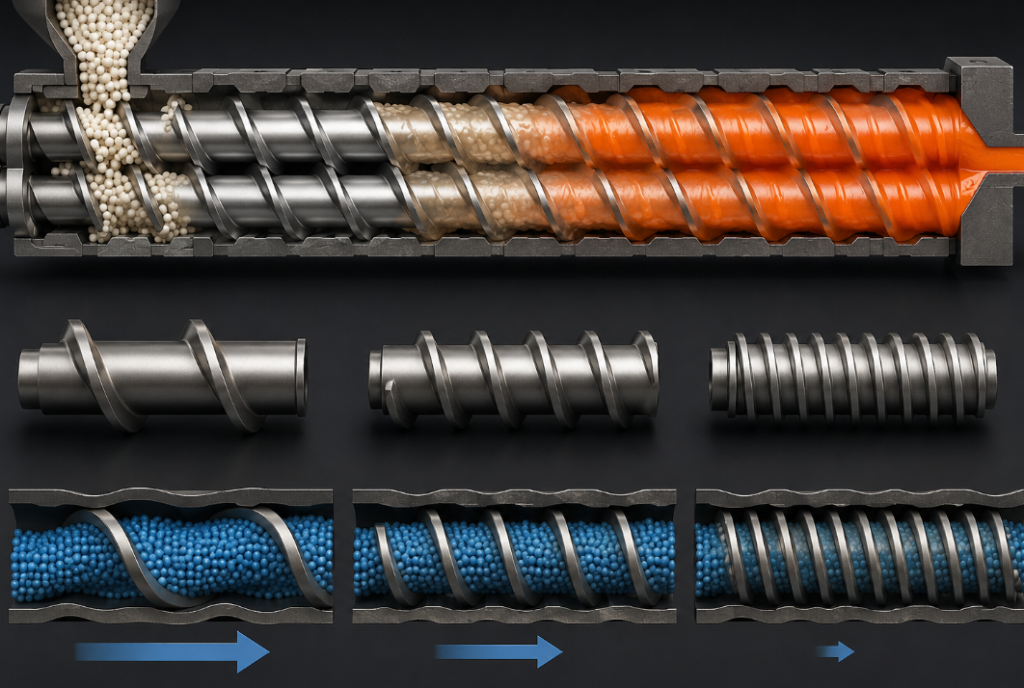
Before you can build a configuration, you need to understand the toolkit. There are three broad categories of screw elements in a typical co-rotating twin screw system, each with multiple geometric variants. The names and exact dimensions vary by manufacturer, but the functional logic is universal.
Conveying Elements — The Workhorses That Keep Material Moving Forward
Conveying elements — sometimes called forwarding elements — are helical screw flights that push material downstream. Their key variables are pitch (the axial distance one flight advances per full rotation) and flight depth (how much free volume they create). High-pitch elements move material quickly with low shear; low-pitch elements slow things down and build pressure. They’re typically used at the feed zone, in transition zones between processing sections, and just before the die where you need pressure buildup without excessive heat generation.
Kneading Blocks — Where Real Mixing and Dispersive Work Happens
Kneading blocks — or kneading discs — are the heart of any dispersive mixing zone. Rather than continuous flights, they consist of a series of offset disc-shaped lobes stacked along the shaft. The stagger angle between discs (typically 30°, 45°, 60°, or 90°) controls the intensity and direction of mixing: narrower angles are gentler; 90° creates the most aggressive shearing action. Kneading blocks are where you break down agglomerates, melt polymer, and distribute fillers. The configuration of kneading block screw elements within a processing zone is often the deciding factor in compound quality.
Mixing Elements and Special Geometry — Fine-Tuning Distributive Blending
A third family includes toothed mixing elements, reverse-pitch elements, and gear-type mixing rings. These create distributive rather than dispersive mixing — reorienting and folding the melt stream to improve homogeneity without necessarily applying high shear. Reverse elements can deliberately create pressure-building melt seals upstream of a vacuum vent. Toothed elements increase interfacial area for blending. These special-geometry screw elements are essential for reactive extrusion and polymer blending applications where you need thorough mixing without degrading sensitive components.
Table 1 — Core Screw Element Types: Functional Comparison
| Element Type | Primary Function | Mixing Mode | Shear Intensity | Pressure Build | Typical Zone Placement |
|---|---|---|---|---|---|
| High-pitch conveying | Fast forward transport | None | Low | Low | Feed zone, vent zone |
| Low-pitch conveying | Pressure generation | None | Medium | High | Die approach, metering |
| Kneading block 30° | Gentle melting/mixing | Dispersive | Medium | Medium | Melting zone, sensitive materials |
| Kneading block 60° | Balanced mixing | Dispersive + Distributive | Medium-High | Medium | Filler incorporation zones |
| Kneading block 90° | Intensive shear mixing | Dispersive | High | Low | Pigment dispersion, agglomerate breaking |
| Reverse kneading block | Melt sealing / back-mixing | Distributive | High | Very High | Before devolatilization vents |
| Toothed mixing element | Interface multiplication | Distributive | Low | Low | Blending, color incorporation |
| Reverse conveying | Back-pressure / sealing | None | Medium | Very High | Before liquid injection ports |
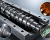
Modular screw element assembly showing conveying segments, kneading block arrays, and mixing discs arranged along a co-rotating twin shaft.
How Your Raw Material Properties Should Dictate the Entire Screw Elements Configuration Layout from Feed to Die
Here is where most buyers go wrong: they describe what they want to produce rather than what they’re feeding into the machine. A supplier who asks only about your target output and ignores your raw material properties will give you a generic configuration that works adequately — but rarely optimally.
The material properties that matter most are melt viscosity, thermal sensitivity, filler loading and particle hardness, moisture content, and the presence of reactive functional groups. Each of these pulls the optimal screw element configuration in a different direction.
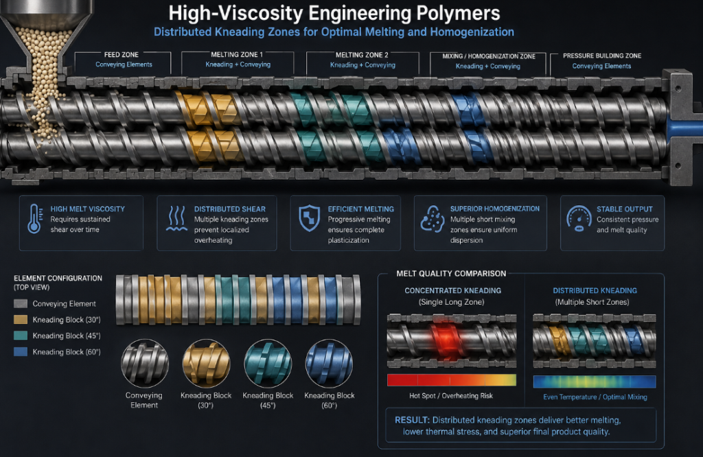
High-Viscosity Engineering Polymers and the Case for Distributed Kneading Zones
Materials like PC, PEEK, and PA66 at high molecular weights need sustained shear over time — not one brutal shear event. The best configurations for these materials spread kneading block screw elements across multiple shorter zones rather than concentrating all the mixing in one long section. This prevents localized overheating while ensuring adequate melting and homogenization.
Glass Fiber Reinforced Compounds and the Careful Balance Between Dispersion and Fiber Integrity
Glass fiber is where screw elements for glass fiber reinforced materials face their hardest test. You need enough shear to wet the fiber surface and break up bundles, but too much shear destroys fiber length — and fiber length is the primary driver of mechanical strength. Standard practice is to feed fiber downstream (via a side feeder) after the initial melting zone, then use only gentle conveying elements and low-angle kneading blocks in the fiber-incorporation section. Short, low-pitch conveying elements near the die preserve average fiber length.
Soft PVC and Rubber Compounds That Demand Temperature-Controlled Gentle Processing
Thermally sensitive materials like plasticized PVC, TPE, and natural rubber compounds can degrade in seconds if shear heat exceeds a threshold. These applications benefit from wide-pitch conveying elements that minimize residence time, combined with very short 30° kneading blocks placed strategically rather than continuously. The custom screw elements for polymer compounding of these materials often use materials with superior thermal conductivity in the element body itself to help pull heat out rather than accumulate it.
Table 2 — Material Type vs. Recommended Screw Elements Configuration Strategy
| Material Type | Key Challenge | Recommended Kneading Block Angle | Conveying Pitch | Filler Feed Point | Special Considerations |
|---|---|---|---|---|---|
| PP / PE compounds | Low melt strength, easy to overheat | 45°–60° | Medium | Main feed | Short kneading zones; avoid excessive residence time |
| PA6 / PA66 | Moisture sensitivity, high viscosity | 45°–60° | Medium-Low | Downstream side feeder | Devolatilization vent required; melt seal before vent |
| PC / ABS blends | Immiscibility, thermal sensitivity | 45° + 90° combo | Medium | Main feed | Distributive mixing elements essential for phase morphology |
| GF-reinforced PA/PP | Fiber breakage vs. dispersion | 30° post-fiber zone | High after fiber | Downstream side feeder | Low-shear elements after fiber introduction; preserve length |
| Carbon black masterbatch | Aggregate breakup; dusty feed | 60°–90° | Low-Medium | Main or starve-fed | Intensive kneading early; reverse element for melt seal |
| Soft PVC / TPE | Thermal degradation | 30° short blocks only | High | Main feed | Minimize residence time; barrel cooling critical |
| PEEK / high-performance polymers | Very high processing temp; abrasion of elements | 45° | Low | Main feed | Wear-resistant screw elements mandatory; HIP-treated surfaces |
| Reactive extrusion (grafting, coupling) | Residence time control; reactant distribution | 45° + toothed mixers | Variable | Liquid injection port | Reverse element before injection; long distributive mixing zone |
The Five Critical Design Parameters You Must Nail Before Finalizing Any Screw Elements Configuration for a Custom Order
Talking to a screw element supplier for the first time can feel overwhelming — there are hundreds of individual geometry options, and every manufacturer has slightly different naming conventions. But underneath all that complexity, five design parameters govern most of the performance tradeoffs you’ll need to make.
Pitch Ratio — The Single Number That Controls Your Balance Between Throughput and Shear
Pitch ratio is the ratio of the flight pitch to the screw outer diameter. High pitch ratios (1.5–2.0) give you fast material transport and low shear — ideal for the feed zone and before vent ports. Low pitch ratios (0.5–0.75) generate high pressure and increase fill degree, boosting shear. Optimizing screw elements pitch ratio and flight geometry is almost always the first tuning step when you’re troubleshooting output instability.
Stagger Angle in Kneading Blocks — What Determines Whether You Get Dispersive or Distributive Mixing
We’ve touched on this already, but it bears repeating in the context of configuration design: you should think of stagger angle as a dial between “break things apart” (high angle, dispersive) and “fold things together” (low angle, distributive). Most real compound formulations need both, which is why experienced engineers stack different kneading block angles in sequence rather than using a single angle throughout the mixing zone.
Number and Width of Kneading Discs — Controlling Residence Time Inside the Mixing Zone
A kneading block with more, thinner discs provides more mixing events per unit length. Fewer, wider discs provide fewer events but allow more material through per rotation. For highly loaded compounds — high filler levels or high-viscosity polymers — wider discs reduce the risk of pressure spikes. For color concentrate and masterbatch production where dispersion quality is paramount, more discs give you better agglomerate breakdown.
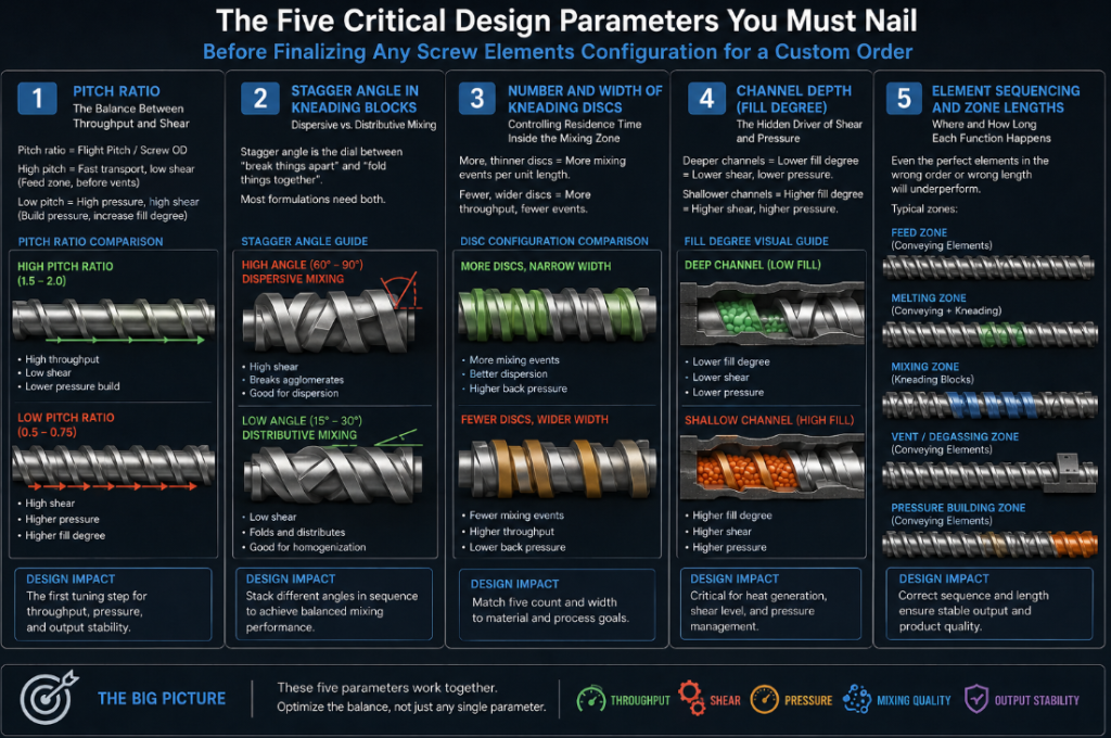
Table 3 — Key Screw Element Design Parameters and Their Performance Impact
| Parameter | Low Value Effect | High Value Effect | Primary Impact On | Tuning Priority |
|---|---|---|---|---|
| Pitch ratio | Slow transport, high fill degree, high shear | Fast transport, low fill degree, low shear | Throughput, shear energy, pressure | Critical |
| Kneading stagger angle | Gentle mixing, higher forward conveying | Intensive dispersive mixing, low forwarding | Mixing quality, melt temperature | Critical |
| Number of kneading discs | Higher throughput, less mixing events | More mixing events, potential overheating | Dispersion quality, residence time | High |
| Disc width ratio | More intensive per-disc shear | More distributive, less per-disc intensity | Shear rate distribution | High |
| Flight clearance (tip clearance) | Intense shear, more heat generation | Lower shear, more leakage flow | Shear intensity, element wear rate | High |
| L/D of mixing zone | Shorter residence time, less total energy | Longer residence, more thorough mixing | Degree of mixing, throughput | Moderate |
| Number of flight starts | More free volume (single-flight) | Less free volume, higher pressure (bi-lobe/tri-lobe) | Fill degree, self-wiping efficiency | Moderate |
Engineering note: Never optimize these parameters in isolation. A high stagger angle with a narrow tip clearance on high-filler compounds is a recipe for catastrophic overheating. Always treat the configuration as a system — each element choice affects what comes before and after it.
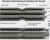
Cross-sectional view of a co-rotating twin screw barrel showing the intermeshing geometry and clearance zones between element lobes and barrel wall.
Comparing Screw Elements Performance Across Key Industries and How Processing Conditions Change Everything
Different industries have radically different definitions of “good performance.” A screw configuration that produces excellent carbon black dispersion for masterbatch would likely destroy the fiber integrity in a glass-filled automotive compound. Industry context is everything, and understanding the performance benchmarks in your sector helps you evaluate supplier configurations more critically.
Table 4 — Screw Elements Performance Comparison Across Major Industries
| Industry / Application | Primary Performance Metric | Element Configuration Priority | Typical Screw Speed | Critical Screw Element Feature | Common Failure Mode |
|---|---|---|---|---|---|
| Automotive engineering compounds (GF/CF filled) | Fiber length retention ≥ 0.3 mm average | Fiber preservation | 200–350 rpm | High-pitch elements after side feeder | Over-shearing fiber during incorporation |
| Color & additive masterbatch | Dispersion quality (filter pressure build) | Intensive mixing | 400–600 rpm | 90° kneading blocks + reverse element | Poor pigment wetting; color streaking |
| Food-grade extrusion (starch, PVOH) | No metal contamination; texture consistency | Gentle mixing + hygiene | 150–300 rpm | Food grade screw elements with polished surfaces | Corrosion from moisture/acid |
| Reactive extrusion (maleic anhydride grafting) | Grafting efficiency %; molecular weight preservation | Reaction zone control | 200–400 rpm | Toothed mixers + liquid injection port setup | Incomplete reaction; degradation from excess shear |
| Devolatilization / degassing | Residual monomer / VOC level (ppm) | Surface renewal rate | 300–500 rpm | Reverse element before vent; deep-flight elements at vent | Melt flooding the vent port |
| Cable insulation compounds (XLPE, HDPE) | Gel count; long-term voltage stability | Low shear, thorough melting | 100–250 rpm | Gentle kneading blocks; no sharp reverse elements | Gel formation from stagnation zones |
| High-filled compounds (≥50% CaCO₃ or talc) | Uniform filler distribution; surface finish | Dispersion + throughput balance | 300–450 rpm | High-torque screw elements performance with wear protection | Abrasive wear; output surge |
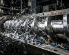
Sectioned screw shaft after extended run in a high-filled mineral compound showing wear patterns at kneading block tips — a common diagnostic in abrasive material applications.
Screw Element Base Materials and Surface Treatments — Why the Metal You Choose Determines Long-Term Cost Per Kilogram
Element geometry gets all the attention, but material selection is where the long-term economics of a screw configuration are decided. A geometrically perfect screw element made from the wrong base material can wear out in weeks under abrasive conditions. Conversely, premium wear-resistant alloys on a gentle application are unnecessary cost.
Wear in screw elements occurs through three mechanisms: abrasive wear (hard filler particles scratching the element surface), adhesive wear (metal-on-metal contact under high pressure), and corrosive wear (chemical attack from reactive polymers, moisture, or flame retardants). Real-world applications often combine all three, which is why wear resistant screw elements for abrasive materials need to be specified with all three mechanisms in mind, not just abrasion resistance.
Table 5 — Screw Element Material Grades and Surface Treatment Comparison
| Material / Treatment | Hardness (HRC) | Abrasion Resistance | Corrosion Resistance | Max Temp. (°C) | Typical Application | Relative Cost |
|---|---|---|---|---|---|---|
| Standard tool steel (P/M) | 58–62 | Moderate | Low | 300 | General-purpose; unfilled polymers | Low |
| High-speed steel (M2/M4 grade) | 62–65 | Good | Moderate | 350 | Moderately filled compounds | Medium |
| Bimetallic (HIP sintered carbide shell) | 65–70 | Excellent | Good | 400 | GF/CF compounds; mineral-filled masterbatch | High |
| Solid tungsten carbide | 70–75 | Outstanding | Good | 450 | Heavily abrasive: silica, carbon black, glass bead | Very High |
| Corrosion-resistant stainless alloy (316L base) | 40–50 | Low | Excellent | 350 | Food grade screw elements; medical polymers; PVC | Medium |
| Nickel-based alloy (Hastelloy-type) | 45–55 | Moderate | Excellent | 500+ | Fluoropolymer processing; highly corrosive formulations | Very High |
| PVD/CVD hard coating on tool steel | 75–85 (surface) | Very Good | Good | 300 | Cost-performance balance; medium-filled compounds | Medium-High |
A practical rule of thumb: if your filler loading exceeds 30% by weight, or if you’re processing any fiber-reinforced compound, bimetallic elements with a tungsten carbide or equivalent hard phase should be your starting point, not your upgrade. The additional upfront cost is recovered within months through reduced downtime and rebuild frequency.
Configuration Mistakes That Cost Manufacturers Thousands — and How to Avoid Repeating Them
After years of working with compounders across plastics, rubber, and food processing, the same configuration errors appear repeatedly — regardless of the size of the operation. They’re worth naming directly.
Copying a competitor’s configuration without understanding why it works. Configuration knowledge is proprietary for a reason. A kneading block sequence that gives excellent dispersion at 400 rpm on one machine may generate catastrophic overheating at the same speed on a different barrel diameter. Always start from material properties, not borrowed settings.
Under-specifying the feed zone when running high-bulk-density materials. A tight pitch at the feed throat starves the machine and creates inconsistent fill — even with a powerful feeding system. The feed zone needs to be the most generous part of the screw, and many buyers overlook this when specifying modular screw elements design for reactive extrusion or other specialty processes where attention tends to drift toward the chemistry zone.
Ignoring the vent zone design. A melt seal before a vacuum vent requires a reverse element or a deliberately under-filled zone to prevent melt from being drawn up into the vent. This is a system design issue — not just a screw element choice — but the wrong element selection here causes expensive vent blockages.
Specifying only one material grade across the entire screw. In a typical configuration, the feed zone faces very different stresses than the intensive mixing zone. Specifying a single element material grade across the whole build is rarely optimal. A segmented approach — standard grade in the feed and discharge zones, wear-resistant grade in the mixing and filler-incorporation zones — balances cost against performance far more effectively.
Detail of a screw element rebuild showing the progression from worn kneading discs to newly installed bimetallic replacements — demonstrating the value of zone-specific material specification.
How to Work Effectively with a Screw Elements Supplier When Placing a Custom Configuration Order
The conversation you have before submitting a purchase order determines more of your outcome than the order itself. Suppliers who specialize in screw elements for masterbatch and color concentrate production, for example, will design differently from those whose reference customers are all in the automotive space. The more precisely you communicate your process requirements, the better the configuration you’ll receive.
Before contacting a supplier, prepare a brief with the following information: your extruder make, model, and screw diameter; your base polymer and filler/additive loading by percentage; your current throughput and target throughput; your current screw speed and temperature profile; any quality problems you’re trying to solve; and your rebuild frequency under current conditions.
From this brief, a competent supplier can propose a configuration, select element grades, and estimate expected service life. Ask for a simulation or flow analysis if the supplier offers it — CFD-based screw design has become accessible enough that reputable manufacturers routinely use it for new builds. If a supplier quotes you purely from a catalog without asking about your material, be cautious.
“The best supplier relationships work more like an engineering partnership than a parts transaction. You share your process data; they share configuration logic. Both sides learn, and the compound quality shows it.”
Also ask specifically about interchangeability. The best suppliers design their screw elements to be compatible with major extruder platforms — Coperion, Leistritz, Berstorff, and others — even when the elements are manufactured independently. Proprietary fit-only elements lock you into a single supplier chain; compatible elements give you flexibility.
Frequently Asked Questions About Screw Elements Selection, Configuration, and Custom Orders
How do I know if my current screw elements configuration is actually causing my quality problems, or if something else is the culprit? ›
Start with a controlled diagnostic: run your current material at a reduced throughput (around 60% of normal) and see if the quality problem diminishes. If it does, the issue is almost certainly shear-related — either too much or too little — and your screw element configuration is the primary suspect. If the problem persists at reduced throughput, look at barrel temperature profiles, feed consistency, and resin batch variation first. Screw elements are the right target when the problem tracks with output rate, screw speed, or when you see localized melt temperature spikes in your data logging. What is the typical service life of screw elements in a high-filled compound application, and what factors have the biggest influence on that lifespan? ›
For high-filled compounds — anything above 40% calcium carbonate, talc, glass fiber, or similar hard fillers — service life on standard tool steel elements can be as short as 500–1,000 operating hours. Bimetallic elements with HIP-processed tungsten carbide shells routinely achieve 3,000–8,000 hours in the same application, which is why they command a price premium that pays for itself. The factors with the greatest influence on service life are filler hardness (Mohs scale), filler particle sharpness, tip clearance specification, and screw speed. Slowing down the screw by even 10–15% can extend element life significantly in borderline abrasive applications, often without any meaningful throughput penalty. Can screw elements from one manufacturer fit a twin screw extruder barrel made by a different brand, and what should I verify before ordering? ›
Yes — in the majority of cases, third-party screw elements are designed to be dimensionally compatible with major extruder platforms, including Coperion, Leistritz, KraussMaffei Berstorff, and others. The critical dimensions to verify are outer diameter (OD), root diameter or bore ID, spline profile (the internal profile that mates with the screw shaft), and element length. Most manufacturers supply a compatibility chart or can confirm fitment if you provide the extruder OEM, model number, and shaft diameter. Always request a first-article inspection certificate and fit-check protocol when ordering elements for a new platform for the first time. Is it worth investing in a full simulation or CFD analysis of a new screw elements configuration before committing to a build, especially for a custom application? ›
For standard applications on well-characterized materials, a simulation is useful but not always essential — an experienced supplier can draw on reference configurations that are well-tested. But for genuinely novel applications — reactive extrusion, new polymer blends, highly unusual filler combinations, or very tight product specs — a CFD or residence time distribution simulation can prevent expensive trial-and-error on the production floor. The cost of a competent simulation (typically a few thousand USD) is almost always far less than the cost of one or two failed trial builds plus associated downtime. Think of it as an insurance policy on your capital investment. What information should I prepare before requesting a custom screw elements quotation, and how specific do I need to be about my process parameters? ›
Be as specific as possible — but don’t let gaps stop you from starting the conversation. The minimum a supplier needs to give you a meaningful proposal includes: extruder brand and model, screw diameter and L/D ratio, base polymer type, filler type and loading percentage, target throughput range, and the primary quality challenge you’re trying to address (dispersion, fiber length, temperature control, etc.). If you can also share current screw speed, melt temperature at the die, and any existing wear pattern observations, the supplier can dramatically sharpen the configuration recommendation. For high-volume custom applications, some manufacturers will also request a material sample for laboratory extrusion trials before finalizing the configuration design.