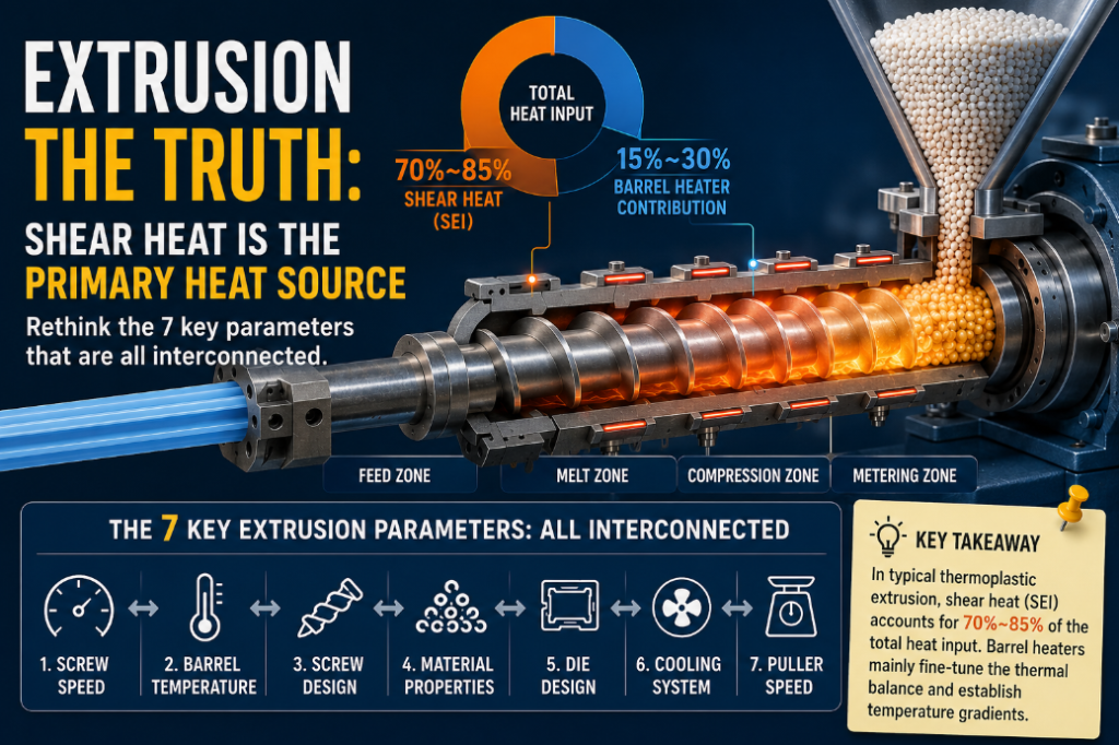
Step into any plastic extrusion workshop and observe the most common “process adjustment.” The first instinct of most floor engineers is to tweak the barrel zone temperatures—lowering the downstream temperature if the product is too brittle, or raising the upstream temperature if the material flow is unsmooth. This operational logic operates on a hidden assumption: that barrel heaters are the primary source of thermal energy for the material.
Under conventional extrusion conditions for the vast majority of thermoplastic polymers, this assumption is fundamentally flawed.
The primary source of heat in the melt is actually the shear heat—professionally termed Specific Energy Input (SEI)—generated by the motor-driven screw overcoming the viscous resistance of the melt. In standard single-screw extrusion of general-purpose resins like PE, PP, and PS, it is entirely common for shear heat to account for 70% to 85% of the total heat input. During steady-state operation, barrel heaters primarily serve to “fine-tune the thermal balance” and “establish zonal temperature gradients,” rather than actively “heating the plastic.” Only under specific conditions—such as with small laboratory extruders, exceptionally low screw speeds, high-melting-point engineering plastics, or extrusion coating—do heaters approach the status of a primary heat source.
Understanding this is not merely an exercise in correcting terminology; it is the prerequisite for recalibrating the relationships between all subsequent processing parameters. Once the false premise of the “barrel heater as the main heat source” is removed, you will realize that the 7 key extrusion parameters are never isolated variables, but rather an interconnected, coupled network revolving around energy and mass flow.
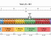
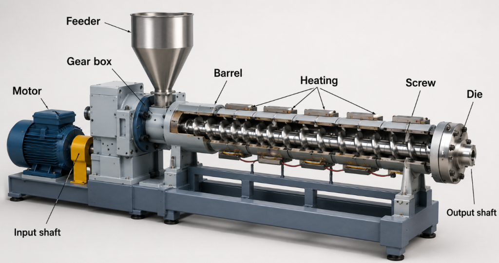
A simplified technical illustration of a single-screw plastic extrusion process
I. The Framework: 4 Underlying Variables Behind the 7 Parameters
No matter how the 7 process parameters are adjusted, they ultimately affect product quality and throughput by influencing the following 4 underlying variables:
- Residence Time: The duration the material spends inside the barrel from feed to discharge. It dictates the completeness of melting, the progress of chemical reactions, and the risk of thermal degradation.
- Degree of Fill: The actual percentage of the screw channel occupied by the material (typically 30%–70% for twin-screw extruders). It determines mixing intensity, pressure-building capability, and motor load.
- Shear Heat (Specific Energy Input): The mechanical energy imparted per unit mass of material. It dictates melt temperature, viscosity, and potential polymer degradation.
- Mixing Quality: The level of both distributive mixing (macroscopic uniformity) and dispersive mixing (microscopic breakdown). It determines the final mechanical properties of compounds, blends, and masterbatches.
The discussion of each parameter below will refer back to these 4 variables. The root cause of almost any throughput or stability issue can be traced back to these four dimensions.
II. Parameter 1: Raw Material Moisture Content & Pre-treatment
Many product defects erroneously blamed on “extrusion processing” actually originate before the material even enters the feed throat.
When hygroscopic resins (e.g., PA6, PA66, PET, PC, PMMA, TPU) exceed their moisture tolerance, two major issues arise simultaneously. First, water vaporizes at high temperatures, causing bubbles, splay marks (silver streaks), and surface defects. Second, hydrolytic degradation occurs. In PET, for example, a moisture content exceeding 0.02% will trigger significant polymer chain cleavage, causing a sharp drop in Intrinsic Viscosity (IV) and a collapse in the mechanical properties of the final product.
Baseline Moisture Targets for Common Resins:
| Resin | Drying Temperature | Drying Time | Target Moisture Content |
| PET | 150–170°C | 4–6 h | < 0.005% |
| PA66 | 80–100°C | 4–6 h | < 0.10% |
| PC | 110–120°C | 3–4 h | < 0.02% |
| PMMA | 80–90°C | 2–4 h | < 0.04% |
| ABS | 80–90°C | 2–3 h | < 0.10% |
| TPU | 80–110°C | 2–3 h | < 0.03% |
A critical warning: “Feeling dry” does not equal “process dry.” Leaving hygroscopic resins exposed to ambient workshop air for just 1–2 hours after opening can cause moisture levels to rebound to unacceptable levels. It is highly recommended to use desiccant dryers capable of maintaining a dew point below -40°C, and to monitor moisture inline, rather than relying solely on hot-air circulating hopper dryers.
Impact on the Coupled Network: Excess moisture artificially elevates shear heat (vaporization absorbs heat, forcing the system to demand a higher melt temperature to compensate) and disrupts mixing quality via bubble formation. It impacts at least 3 of the 4 underlying variables.
III. Parameter 2: Feed Rate & Feeding Stability
The feed rate sets the physical ceiling for output, but feeding stability dictates the ceiling for product quality.
In twin-screw processes, the feed rate and screw speed jointly determine the degree of fill. If the fill degree is too low, the material slips between the screw elements, failing to build adequate pressure, resulting in poor dispersion and mixing. If the fill degree is too high, it can cause die pressure surges, motor overload, and in severe cases, catastrophic damage to the thrust bearings. Engineering best practices for co-rotating twin screws dictate maintaining a steady-state degree of fill between 30% and 70%.
Feeding systems generally fall into two categories:
- Volumetric Feeding: Relies on a screw or rotary disc to deliver material by volume. It is simple and cost-effective, with an accuracy of ±2%–3%. However, it is highly sensitive to fluctuations in bulk density. (For instance, virgin PP and regrind PP of the same grade can vary in bulk density by 5%–10%, introducing an equivalent error in the feed rate).
- Loss-In-Weight (LIW) Feeding: Utilizes real-time load cell feedback to adjust screw speed, achieving accuracies up to ±0.5%. This is the industry standard for multi-component precision compounding, masterbatches, and medical-grade extrusion.
The chain reaction of feeding fluctuations is short and brutal: Feed Fluctuation $\rightarrow$ Fill Degree Fluctuation $\rightarrow$ Shear Heat Fluctuation $\rightarrow$ Melt Temperature Fluctuation $\rightarrow$ Melt Pressure Fluctuation $\rightarrow$ Product Dimension/Property Fluctuation. A vast majority of “random quality issues” on the production line trace back to feeding instability, not barrel processing parameters.
IV. Parameter 3: Screw Geometry (L/D, Compression Ratio, Clearance)
The screw is the “heart” of the extruder. While its geometric parameters are largely locked in during the equipment procurement phase, understanding them is vital for process optimization.
- L/D Ratio (Length-to-Diameter): Typically 20–30 for single screws, 36–48 for twin screws, and up to 56+ for reactive extrusion. A higher L/D provides more time for complete melting, more axial space for mixing elements, and better devolatilization. However, it also results in longer residence times and higher accumulated shear heat, which is highly detrimental to heat-sensitive polymers like PVC or POM.
- Compression Ratio: The ratio of the flight volume in the feed section to the metering section (typically 2.5–4). It forces out entrapped air and promotes melting by gradually constricting the screw channel. Semi-crystalline polymers (PE, PP, PA) require higher ratios (3–4) to ensure complete melting. Amorphous or heat-sensitive resins (PVC, CPE) require lower ratios (1.6–2.5) to prevent localized thermal degradation.
- Radial Clearance (Screw-to-Barrel Gap): The standard clearance is roughly 0.001 to 0.002 times the screw diameter (e.g., for a Φ65 screw, the gap is roughly 0.065–0.13 mm). This seemingly minute parameter has a massive impact on output. Theoretical modeling shows that leakage flow increases approximately as a cubic function of the clearance gap. If a machine runs well when new but experiences a “slow decline in output” over 2-3 years, a worn barrel/screw gap exceeding 0.3 mm is usually the true culprit—often misdiagnosed as “motor aging” or “heater drift.”
Wear has a secondary consequence: increased leakage flow means the screw must rotate faster to maintain the same output. This artificially inflates shear heat, forces the melt temperature up, and causes polymer properties to drift. Periodically measuring screw wear and establishing a replacement baseline (e.g., refurbishing or replacing when radial wear reaches 0.5%–1% of the diameter) is the most underrated practice in stabilizing legacy extrusion lines.
V. Parameter 4: Barrel Zonal Temperatures
Returning to our prologue: if shear heat is the primary heat source, what is the actual function of barrel temperature profiling?
- Upstream (Feed Zone): Controlling “Solid Conveying”In the feed zone, the material exists as solid pellets. The core function of the barrel wall temperature here is to manipulate the friction coefficient between the pellets and the barrel, and between the pellets and the screw root. To maximize the solid conveying rate in a single-screw extruder, pellets must adhere to the barrel wall and slide against the screw. This means the barrel wall should run slightly cooler than the screw root, preventing pellets near their melting point from prematurely adhering to the screw and causing a “bridge.”Common mistake: When feeding is unstable, operators often raise the feed zone temperature. Consequently, resins like PE or PP melt prematurely at the feed throat, adhere to the screw root, and solid conveying plummets. The correct approach is to keep the feed zone 30°C–50°C below the melting point and ensure robust screw root cooling (e.g., internal water cooling).
- Midstream (Melting/Compression Zone): Thermal BalancingThis zone works in tandem with the screw’s compression section to finalize melting. This is where shear heat generation is most violent. The barrel temperature here often acts more as a “cooling sink” rather than a “heater,” utilizing cooling blowers or water jackets to prevent the shear heat from pushing the melt past its degradation threshold.
- Downstream (Metering Zone) & Die: Dictating Final Melt TemperatureBy this stage, the polymer is fully molten and homogenized. The temperature setpoints here should essentially match your target melt temperature. These should be reverse-engineered from your final melt target, not set by “gut feeling.”
The True Diagnostic Tool: Melt Temperature vs. Barrel Temperature
Thermocouples mounted on the outer barrel wall measure the steel temperature, which can deviate from the actual melt temperature by 10°C–30°C (and up to 50°C in high-shear conditions). Relying solely on the barrel temperature readout is like diagnosing a machine while looking through a frosted window—it is delayed and biased. Installing a melt temperature probe (flush-mounted or infrared) right before the die and using it as the primary variable for closed-loop control is highly recommended.
VI. Parameter 5: Melt Pressure & Back Pressure
Melt pressure is the most vital “vital sign” of the extrusion process. Its steady-state value before the die reflects the process balance, while its amplitude of fluctuation reflects process stability.
Under normal conditions, steady-state melt pressure fluctuations should be kept within ±2%. If sustained, amplified fluctuations occur, the transmission chain is typically one of the following:
- Cyclic Fluctuation: Feed fluctuation $\rightarrow$ Fill degree fluctuation $\rightarrow$ Periodic pressure surging (frequency correlates to the feeder screw speed).
- Slow, Linear Increase: Gradual clogging of the screen pack or melt filter.
- Sudden Step-Increase: Partial blockage in the die runner or a sudden cold spot.
- Inability to Build Pressure: Localized wear in the screw/barrel leading to severe leakage flow.
Back pressure is an actively adjustable parameter in compounding and injection molding. In twin-screw extrusion, back pressure is manipulated via die geometry, screen pack density, and breaker plate design. Increasing back pressure elongates residence time and intensifies distributive mixing, but simultaneously reduces throughput and spikes shear heat. This is a classic multi-objective trade-off.
Recommendation: Install a melt pressure transducer before the die on every production line and integrate it into a DAQ (Data Acquisition) system. A 7-day pressure trend curve provides more insight than any subjective operator diagnosis.
VII. Parameter 6: Vacuum Degassing (Venting)
Degassing is frequently overlooked, yet for engineering plastics, fiberglass compounding, recycling processes, and reactive extrusion, venting efficiency directly dictates the yield rate.
Effective venting relies on three core elements:
- Positioning: In twin screws, the vent is typically located in a specialized screw section where melting is complete and the melt has decompressed (typically around 60%–80% of the L/D). Single screws utilize specialized two-stage vented screw designs. Incorrect positioning causes the polymer to surge out of the vent (known as vent flooding).
- Vacuum Level: Typical industrial vacuum levels range from -90 kPa to -100 kPa (approaching 0 mbar absolute pressure). High vacuum effectively strips moisture, residual monomers, and degradation byproducts. However, if the vacuum is too strong while the melt viscosity is low, the risk of vent flooding spikes. This is why the degree of fill in the venting zone must be kept below 30%.
- Screw Configuration: The venting zone must utilize deep-flighted, low-shear, forward-conveying elements to maintain a low degree of fill and prevent pressure buildup that would otherwise force volatiles back into the melt matrix.
Troubleshooting Venting Failures:
- Black Specks / Carbonization: Volatile entrapment + Localized stagnation + High-temperature degradation.
- Splay Marks / Surface Ripples: Moisture vaporized but not evacuated in time.
- Bubbles / Low Density: Residual low-boiling-point volatiles (monomers, solvents).
- Inconsistent Mechanical Properties: Fluctuating volatile retention across different batches.
VIII. Parameter 7: Die / Extrusion Head
The die is the “last mile” of the extrusion process. Every instability originating from the upstream 6 parameters will be amplified and exposed at the die lip.
- Die Temperature: As a starting point, set the die temperature to the target melt temperature ±5°C, then fine-tune based on the extrudate appearance. A die temperature that is too cold causes the melt edge to freeze, inducing melt fracture (sharkskin). A temperature too high causes excessive relaxation, dimensional instability, and loss of surface gloss.
- Runner Design: Achieving a uniform velocity distribution across the profile is the ultimate goal. Any dead zones in the flow channel will become stagnation areas: Stagnation $\rightarrow$ Extended Residence Time $\rightarrow$ Thermal Degradation $\rightarrow$ Black Specks & Discoloration. This necessitates CFD (Computational Fluid Dynamics) runner simulations during the design phase and rigorous, periodic manual cleanings during operation.
- Die Lip Land Length: For profile and sheet dies, the land length (typically 10–15 times the die gap) determines the relaxation of flow orientation and final dimensional stability. If the land is too short, the melt stress lacks time to relax, resulting in severe die swell and warping immediately upon exiting the die.
IX. Troubleshooting Priority: When the Process Fails
By mapping out these 7 parameters against common shop-floor defects, we can reverse-engineer a highly practical troubleshooting hierarchy:
Issue 1: Throughput Cannot Reach Target
- Check feeding: Is the feeder maxed out? Is the feeder screw worn?
- Check barrel/screw clearance: Has wear reached a point where leakage flow is dominating?
- Check die/screen pack: Is blockage causing excessive back pressure?
- Only after ruling out the above, investigate motor load and gearbox transmission limits.
Issue 2: Unstable Dimensions or Mechanical Properties
- Check melt pressure fluctuation: Anything exceeding ±2% is abnormal.
- Check feeding stability: Review load cell data and verify if bulk density has shifted.
- Check raw material moisture: Fluctuating moisture = fluctuating melt viscosity.
- Check temperature drift: Particularly focus on die temperature stability.
Issue 3: Black Specks, Splay Marks, and Surface Defects
- Check moisture content: 80% of splay/bubble issues stem from inadequate drying.
- Check vacuum degassing status.
- Check the die runner: Are there dead zones accumulating degraded material?
- Check melt temperature: Is it exceeding the degradation threshold due to excessive shear?
Issue 4: Uneven Mixing or Color Dispersal
- Check feeder accuracy: Crucial for multi-component blending.
- Check screw configuration: Do you have enough dispersive/distributive mixing elements?
- Check back pressure: Does it need to be increased to enhance mixing intensity?
- Check residence time: Is the overall L/D sufficient for the formulation?
Returning to the Coupled Perspective:
The 7 parameters are never seven isolated knobs on a control panel; they collectively and simultaneously act upon Residence Time, Degree of Fill, Shear Heat, and Mixing Quality. Turning any single knob alters at least two or three of these foundational variables. Truly efficient process optimization is not about tuning each parameter to an isolated “perfect” setting, but about achieving a harmonious target balance across the four underlying variables.
Once this is fully grasped, the question of whether the barrel heater is the primary heat source is no longer just a piece of counter-intuitive trivia—it is the first watershed moment marking the transition from an “experienced machine operator” to a true “Process Engineer.”