Carbon fiber-reinforced polymer (CFRP) composites are widely utilized in the aviation, medical, automotive, and shipbuilding industries due to their significant advantages, including low specific gravity, excellent stiffness, high strength, and high-temperature resistance. Twin-screw extrusion has become the primary preparation method for CFRP composites. This is largely due to its outstanding mixing technology, self-cleaning capabilities, and high-yield, low-consumption characteristics, particularly when combined with increasingly mature injection molding and compression molding techniques. This paper evaluates 4 different screw configurations to study the impact of twin-screw arrangements on mixing capacity and extrusion uniformity by comparing residence time, fiber distribution, and fiber length. This research provides valuable guidance for the practical application and process optimization of twin-screw extrusion for CFRP composites.
1. Experimental Section
1.1 Screw Element Arrangements and Configurations
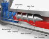
The experiment utilized a co-rotating twin-screw extruder with a conventional reinforcing screw layout.
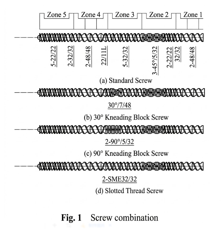
Taking the baseline forward screw (Group a) as an example, the screw is divided into 5 functional zones:
- Materials are fed from Zone 1 and are continuously compacted and transported into Zone 2 by forward screw elements with decreasing pitch.
- Zone 2 consists of three sets of 45° kneading blocks, creating a high-pressure and high-shear area primarily responsible for material melting and initial shearing.
- The sheared material is transported through Zone 3 into the exhaust section in Zone 4. In Zone 4, reverse screw elements build pressure and seal the melt, while large-pitch threads facilitate low-fill material spreading, making it easier to exhaust water vapor and decomposition gases.
- After exhausting, the material is extruded through the small-pitch transfer elements in Zone 5.
While Group a can perform preliminary shearing, it lacks the capability for further intensive shearing and mixing.
To optimize the shearing and mixing capabilities, three alternative configurations (Groups b, c, and d) were designed based on the Group a baseline. Maintaining the same feeding and exhaust sections, the forward screw elements in Zone 3 were modified. Specifically, the 3rd and 4th pairs of 32 mm forward screw elements were replaced with: a 30° kneading block + 22 mm forward screw element (Group b), two sets of 90° kneading blocks (Group c), and two sets of slotted screw elements (Group d).
1.2 Sample Preparation
PA6 resin was first dehydrated in a vacuum drying oven at 110°C for 6 hours. The dried PA6 resin and 5 strands of carbon fiber were simultaneously fed into the twin-screw extruder through the Zone 1 inlet to sequentially prepare samples according to the 4 screw configurations. The screw speed was set to 160 r/min, the PA6 feed rate was 2.5 Hz, and the extrusion temperatures for the 5 zones were set to 240°C, 245°C, 250°C, 245°C, and 240°C, respectively. Cylindrical samples of 40% (mass fraction) carbon fiber-reinforced PA6 composite were produced, and the material residence time was recorded. The extruded strands were then pelletized, dried, and stored for subsequent testing.
1.3 Performance Testing and Structural Characterization
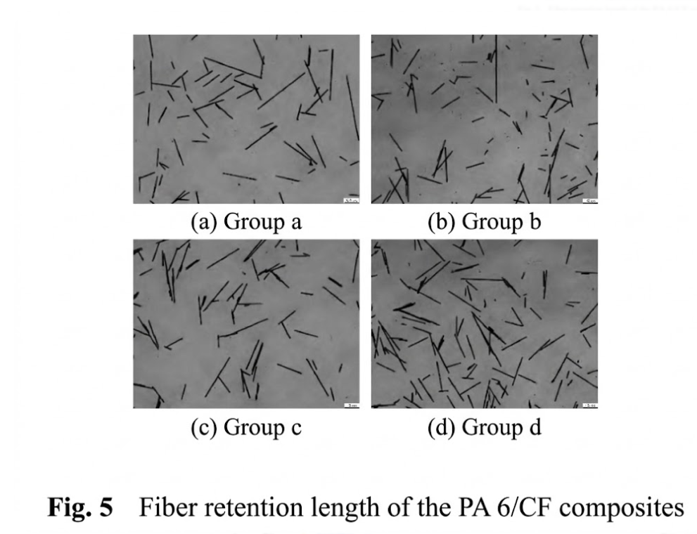
- Carbon Fiber Length Uniformity Test: The extruded pellets were calcined in a muffle furnace at 850°C for 30 minutes to remove the resin. The remaining carbon fiber ash was dispersed using ethanol and a centrifuge. Samples were placed on glass slides, dried, and the retention length of the carbon fibers was observed under a Leica microscope and analyzed using Image Pro Plus.
- Carbon Fiber Distribution Test: Dried pellet samples were embedded and sequentially pre-ground using 1000-grit and 1200-grit sandpaper. The surfaces were then automatically polished for 30 minutes using a 3 μm poly-diamond suspension at 150 r/min and 20 N, followed by another 30 minutes of polishing with a 0.05 μm alumina suspension at 150 r/min and 15 N. The polished surfaces for Groups a, b, c, and d were examined under a Leica microscope.
2. Results and Discussion
2.1 Residence Time Analysis
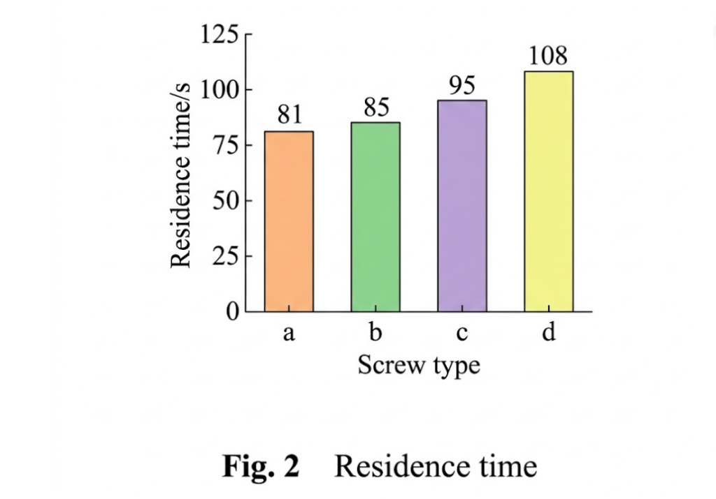
Prolonging the residence time of the melt within the twin-screw barrel allows for more thorough mixing and agitation. Under the same screw speed and feed rate, differences in building pressure and conveying capacity among various screw elements lead to different residence times. The actual material residence time ranked as follows: Slotted screw > 90° kneading block > 30° kneading block > Forward screw.
This occurs because the stagger angle of the kneading blocks causes material exchange between adjacent kneading discs. The larger the stagger angle (e.g., 90° vs. 30°), the larger the gap between adjacent discs, resulting in more severe backflow, decreased conveying capacity, and increased residence time (the 90° block added 10 seconds compared to the 30° block). The slotted screw achieved the best extension of residence time because its unique groove structure generates more backflow than the gaps in kneading discs.
2.2 Fiber Distribution Analysis
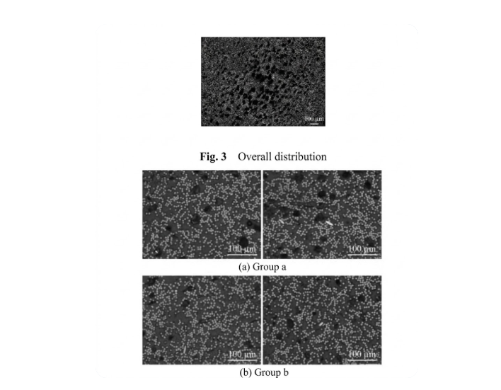
Microscopic observation revealed differences in the skin-core distribution of the pellets. Carbon fibers were denser at the pellet edges but sparser in the center due to the presence of small pores formed by residual water vapor (a result of the extruder providing less pressure compared to an injection molding machine).
At 200x magnification, Groups a and b exhibited obvious dense and sparse zones with chaotic fiber dispersion. In contrast, the fiber distribution in Groups c (90° kneading block) and d (slotted screw) was relatively uniform. This is primarily because the slotted screw and 90° kneading block significantly extended the material’s residence time and enabled the material to undergo dividing/merging and stretching movements, thereby substantially improving material uniformity.
2.3 Fiber Length Analysis

Statistical distribution of the fiber retention length showed that Groups a, c, and d followed a normal distribution between 0~600 μm, with peak values concentrated between 100~300 μm. The 90° kneading block (Group c) and slotted screw (Group d) did not provide stronger shear stress than the 45° kneading block (Group a). Instead, they utilized the extended residence time to thoroughly shear the remaining long fibers, resulting in a more concentrated length distribution that also favors dispersion and mixing within the melt.
Conversely, Group b (30° kneading block) exhibited the highest shear stress. It further sheared the carbon fibers into the 0~100 μm range. While shorter fibers can facilitate dispersion and somewhat improve material uniformity, the excessive cutting of fibers reduces the overall retention length.
3. Conclusions
- Mixing Performance: Slotted screw > 90° kneading block > 30° kneading block > Forward screw. Slotted screws and 90° kneading blocks significantly improve material uniformity by extending residence time and facilitating dividing/merging and stretching movements. While the 30° kneading block has a smaller impact on residence time, it aids mixing by applying greater shear stress to further shorten the fibers.
- Shear Strength: The 30° kneading block generated the highest shear stress, capable of further shortening the carbon fibers. The other three configurations showed little difference in shear strength; the slotted screw and 90° kneading block primarily rely on their extended residence time to fully shear the long fibers missed by the initial screw sections.
- Overall Evaluation: Taking all factors into account, Group d, equipped with slotted screws, is the most beneficial for enhancing material uniformity, achieving a 52% improvement compared to the baseline forward screw.