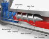
Mastering filler dispersion in PVC profile manufacturing requires more than just standard machinery; it demands precision engineering. An incorrectly specified extruder screw can cause severe thermal degradation, leading to brittle profiles and costly material waste. This ultimate guide details the essential geometric configurations and process parameters needed for perfect compounding. Learn how investing in a customized, wear-resistant bimetallic screw and barrel system not only ensures superior dispersion but also dramatically extends the lifespan of your extrusion line, securing your bottom line against abrasive fillers.
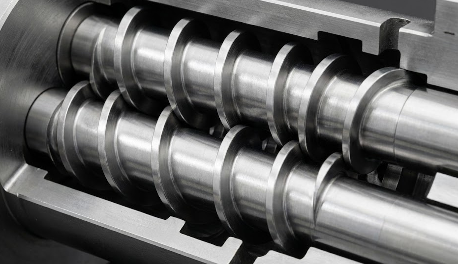
In the high-stakes world of PVC manufacturing, the extruder screw is not merely a component; it is the heartbeat of your entire production line. However, because Polyvinyl Chloride (PVC) possesses a notoriously narrow thermal processing window, the margin for error is virtually non-existent. Selecting an incorrect screw geometry—whether it is a mismatched compression ratio, inappropriate shear elements, or an unsuitable L/D ratio—can lead to catastrophic operational consequences.
Manufacturers utilizing suboptimal screws frequently face severe thermal degradation, resulting in yellowing, black specks, and brittle products that must be scrapped. Beyond the immediate quality issues, the financial toll is staggering: excessive shear heat causes frequent downtime for maintenance, accelerates wear on the barrel, and inflates energy consumption. In an industry where efficiency dictates profit, a wrongly specified screw is a hidden liability that bleeds your bottom line. This guide is designed to navigate these complexities, ensuring your machinery is optimized not just for operation, but for peak performance, superior filler dispersion, and maximum longevity.
1. Single Screw vs. Co-Rotating Twin Screw: Selection Criteria
When processing PVC-U profiles containing 20–40% inorganic fillers like calcium carbonate (CaCO₃), deciding between a single screw and a co-rotating twin screw is the first critical hurdle. The table below provides a straightforward, procurement-oriented comparison to guide your decision.
| Extruder Type | Typical Parameters | Primary Advantages | Potential Limitations | Recommended Scenarios |
| Single Screw | L/D ≈ 22–28:1; Compression Ratio ≈ 2.0–2.5:1 | Simple structure, low initial investment, manageable energy consumption. | Limited geometry-based dispersion; prone to agglomeration and streaking at medium-to-high filler loads. | Low-to-medium filled PVC-U; cost-sensitive lines; applications where static mixers can be added before the die. |
| Co-Rotating Twin Screw | Modular kneading blocks 30–60°; High-filler pitch ≈ 0.8–1.0×D | Forced conveying, excellent self-cleaning, superior sequence-based dispersion (layering-recombining-shearing). | Higher initial investment; improper configuration can lead to rapid, uncontrollable heat generation. | Highly filled PVC/CaCO₃ formulations; profiles requiring strict aesthetic and mechanical consistency. |
2. Geometric and Process Configurations for Filler Dispersion
When “dispersion quality” is your primary objective, both the screw geometry and the processing window must be perfectly dialed in.
- Kneading Block Angle and Pitch: In co-rotating twin screws, 30–60° kneading blocks are frequently used to build sequences of layering, recombination, and controlled shear. Using a smaller pitch (approx. 0.8–1.0×D) in the high-filler section prolongs residence time and increases the probability of breaking up agglomerates.
- End-Stage Micro-Mixing: For single screw extruders, or when trying to improve pigment and fine-powder uniformity further, adding a static or pin mixer before the die head can drastically reduce streaking and uneven temperature distribution (ΔT). Temperature uniformity can often be reduced from ±15°C down to ±2°C.
- Devolatilization Stages: For PVC formulations with moisture-laden fillers or volatiles, it is highly recommended to arrange multi-stage devolatilization (atmospheric + vacuum) at roughly 70–85% of the total L/D, paired with dedicated devolatilization screw elements and strict vacuum control.
- Temperature and RPM Windows: Maintain a stepped or flat-top barrel temperature profile (e.g., 160–185–175°C) and optimize torque and shear heat within the 300–500 rpm range. The goal is to achieve “sufficient shear” alongside a “controlled thermal history”—breaking up agglomerates without degrading or yellowing the PVC.
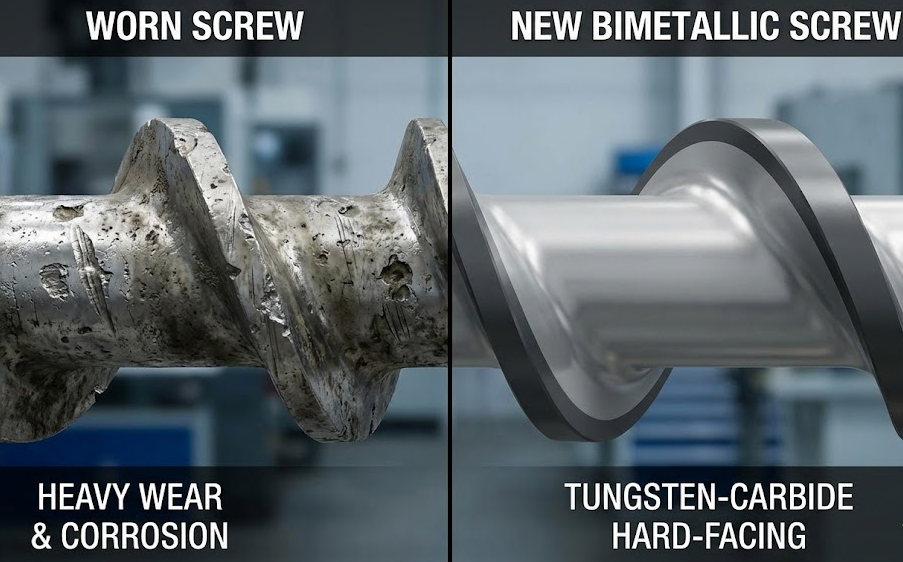
- Wear Resistance and Lifespan: High filler content causes severe abrasion. Utilizing bimetallic barrels and Tungsten Carbide (WC) based screw coatings can increase equipment lifespan by 3 to 5 times.
3. Quantifiable Acceptance KPIs and Test Methods
To ensure the equipment delivers, the following KPIs and testing methods should be written directly into your RFQs and contract appendices as the acceptance criteria for PVC filler dispersion:
- Color Consistency: ΔE (D65/10°) should generally be ≤ 1.5, and ≤ 1.0 for high-consistency architectural profiles. Methods should reference ISO 7724.
- Dispersion Degree: Microscopic image analysis should show an agglomerate volume fraction of ≤ 2–3%, or track the percentage of particles > 10 μm.
- Mechanical Property Retention: Tensile/impact retention rate relative to the baseline formulation should be ≥ 85–90% (referencing ISO 527 for tensile and ISO 179 for impact).
- Surface Defect Rate: The per-piece rejection rate for streaking, white spots, or fish-eyes must be ≤ 1–2%. Online torque fluctuation should remain ≤ ±5%.
- Equipment Lifespan: Suppliers must provide material and hardness specs for the screw/barrel, coating details, wear inspection cycles, and typical lifespan curves.
4. Procurement Terms and Deliverables Checklist
To guarantee that “better dispersion” is a contractual reality rather than a marketing slogan, specify the following deliverables and responsibility boundaries:
- First-Batch Deliverables: Microscopic dispersion photos and statistical reports, ΔE data, mechanical retention rates, process stability logs (torque and melt temperature curves), and material/coating certificates for the screw and barrel.
- Performance Guarantee: If the KPIs (e.g., ΔE > 1.5 or agglomerate fraction > 3%) are not met under specified working conditions, the supplier is responsible for optimizing the configuration, replacing kneading/mixing elements, or accepting returns.
- Standard Referencing: Appearance and physical properties must strictly adhere to relevant ISO or equivalent local standards.
- Commissioning and Acceptance: Clearly define the trial run duration, output windows, and maximum rejection rates. Passing the trial equals acceptance; failing triggers rectification clauses.
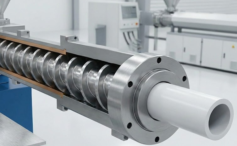
5. Implementation Example: PVC + 30% CaCO₃
- Equipment & Formulation: Co-rotating twin screw ZSK 58, L/D ≈ 44; PVC K=67, CaCO₃ D50 ≈ 3 μm (30 wt%).
- Key Screw Elements: Post-melting: two sections of 30° narrow kneading blocks. Dispersion section: three sections of 45° alternating blocks. Metering section: conveying blocks with a slightly larger pitch. A static mixer is added before the die. Two-stage devolatilization in the middle-rear section (atmospheric + vacuum at approx. −0.09 MPa).
- Process Window: 300–400 rpm; Barrel temperatures around 160–185–175°C; Target residence time of 2–4 minutes.
- Target Thresholds: ΔE ≤ 1.5; Agglomerate volume fraction ≤ 2%; Impact retention ≥ 90%; Defect rate ≤ 1%.
6. Field Verification & Quick Troubleshooting (FAQ)
Q1: What should I check first if the PVC profile surface shows high levels of streaking or fish-eyes?
A: Streaking or fish-eyes indicate poor mixing or localized thermal degradation. First, verify if a static or pin mixer is installed and functioning before the die head. Next, evaluate the kneading section—if it is too short or the block angles are too aggressive, it causes excessive shear heat. Fine-tune the metering section’s pitch and RPM, and consider adding a low-angle kneading block to improve dispersion.
Q2: How do I adjust the extruder if there is a sudden increase in white spots and agglomerates in a highly filled PVC formulation?
A: This points to moisture or poor filler dispersion. Verify the particle size and moisture content of your raw filler. Shift the devolatilization point further downstream and increase the vacuum level. In the high-filler section of the screw, utilize a smaller pitch and narrower kneading blocks to increase residence time and the frequency of material layering and recombination.
Q3: How can I stabilize color consistency (ΔE) during continuous PVC profile production?
A: Color fluctuations are usually caused by uneven mixing or unstable process parameters. Ensure your colorimeter is calibrated and lighting conditions are absolutely consistent. Verify that the feeding systems for lubricants and stabilizers are stable. Finally, optimize the screw speed within your acceptable output window and strongly consider introducing a static mixer to homogenize the melt temperature and pigment distribution.