For any polymer compounding and pelletizing facility, twin-screw extruder downtime is incredibly expensive. In our daily manufacturing operations and technical consultations, one of the most common complaints we hear from plant managers is: “Why are our feed section screw elements wearing out so fast?” Many facilities have resigned themselves to treating feed elements as unavoidable, high-frequency consumables, quietly purchasing replacement batches every few months.
However, as a manufacturing facility that precision-machines these screw components on CNC equipment every day, we must point out a critical truth: Frequent, premature wear is not normal. The vast majority of early feed section failures are caused by incorrect screw geometry configurations or mismatched metallurgical materials.
Drawing from our extensive shop-floor manufacturing experience and real-world client data, this article will dissect the root causes of feed section wear and provide actionable solutions to drastically extend the service life of your components.
Root Causes: Why is the Feed Section a “High-Wear Zone”?
In a twin-screw extruder, the feed section operates in a severely harsh physical environment. The materials here have not yet melted; they are in a hard, solid pellet or powder state. The primary culprits behind rapid element failure include:
1. Severe Abrasive Wear
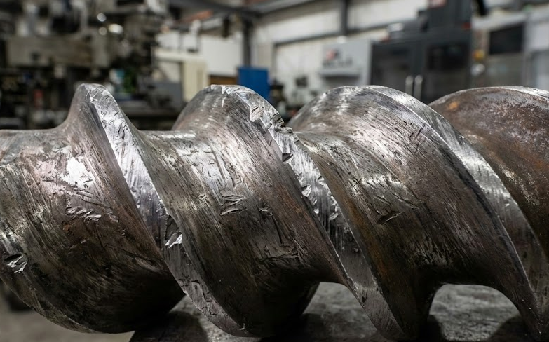
When processing formulations containing high percentages of hard inorganic fillers like Glass Fiber (GF), Calcium Carbonate (CaCO3), Talc, or Titanium Dioxide (TiO2), these cold, solid particles act like microscopic rasps. Driven by the high-speed rotation of the twin screws, they relentlessly gouge the tops of the flight lands and the inner walls of the barrel. This mechanical friction is most intense before the material is fully encapsulated by the polymer melt.
2. Extreme Pressure Spikes in the Compaction Zone
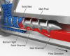
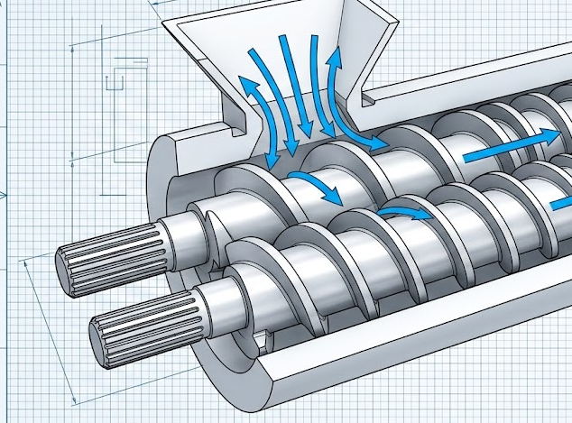
Material drops freely from the feed throat into the screw channels in a loose state. As the screws convey the material forward, the free volume decreases, air is expelled, and the loose powder or pellets are forcibly compacted. If the pitch (lead) reduction is poorly designed, the material forms a “solid plug.” This causes radial and axial pressures to spike instantaneously, multiplying the friction between the metal surfaces and the polymer, sometimes even causing minor screw deflection that rubs against the barrel.
3. Cold Starts and Foreign Objects
In daily operations, if the extruder motor is started before the barrel heaters have fully softened residual polymer, massive torque is instantly applied to the feed elements, easily causing chipped flights or catastrophic breakage. Additionally, tiny metal tramp fragments that bypass magnetic grates are lethal assassins to feed elements.
Solution 1: Eliminating Abnormal Stress Through Geometric Optimization
Solving wear problems starts with physical design. An excellent feed section configuration should act like a perfect funnel—capable of intaking maximum volume while smoothly compacting and transferring it to the melting zone.
Utilize SK Elements (Undercut Feed Elements)
For light powders or materials with poor flowability, SK elements must be positioned directly under the feed throat. Unlike standard conveying elements, the trailing flight flank of an SK element is cut away (undercut), creating a sharper, “shovel-like” profile.
- The Advantage: It aggressively “grabs” the material from above and forces it axially forward, preventing the material from fluidizing or bridging in the feed opening. If powder slips and spins in place here, it not only reduces throughput but also generates intense localized friction heat, accelerating wear.
Implement Smooth Pitch Transitions
To avoid the extreme pressure spikes in the compaction zone mentioned earlier, the reduction in element pitch must be gradual and stepped.
- The Mistake: Jumping directly from a 90/90 (90mm pitch, 90mm length) feed element into a tight 45/45 conveying element is like driving a speeding car into a wall. The localized pressure becomes immense.
- The Factory Optimization: Employ a gradual transition:
90/90 SK->90/90 Standard->60/60 Transition->45/45. This gives the material adequate space to vent entrapped air and compact smoothly, distributing the friction stress evenly across multiple elements.
Strict Clearance and Tolerance Control
As component manufacturers, we know exactly how machining precision dictates lifespan. If the clearance between the screw element and the barrel is too loose (e.g., > 0.30mm), glass-filled melt will aggressively backflow through the gap, causing severe “washout wear.” Conversely, if tolerances are too tight under heavy loads, metal-to-metal galling occurs. Our factory standard strictly controls end-face and radial runout to the 0.02mm level, depending on the extruder diameter, ensuring optimal performance.
Solution 2: Metallurgical Upgrades – Moving Beyond Cheap Nitrided Steel
If geometric configuration is the foundation, metallurgical material is the armor. Continuing to use standard, inexpensive steel for highly abrasive compounding is like throwing money down the drain. Below is the material selection guide our factory utilizes, refined through countless hardness tests and field feedback:
Core Material Comparison for Extruder Feed Elements
| Material Category | Typical Steel Grade | Hardness (HRC) | Abrasive Wear Resistance | Best Application Scenario | Relative Cost |
| Standard Nitrided Steel | 38CrMoAlA | Surface 60-64 (Soft Core) | ⭐ (Poor) | Virgin resin pelletizing, unfilled masterbatch | Low |
| Cold Work Tool Steel | D2 / 1.2379 | 58-60 (Through-hardened) | ⭐⭐⭐ (Moderate) | <15% Glass Fiber or standard CaCO3 | Medium |
| High-Speed Steel (HSS) | M2 / W6Mo5Cr4V2 | 60-62 (Through-hardened) | ⭐⭐⭐⭐ (Good) | 15%-30% Glass Fiber, flame retardants | Higher |
| Powder Metallurgy (PM-HIP) | SAM10 / CPM10V | 62-65 (Uniform Carbides) | ⭐⭐⭐⭐⭐ (Excellent) | >30% Glass Fiber, magnetic materials, engineering plastics | High |
Expert Manufacturing Advice:
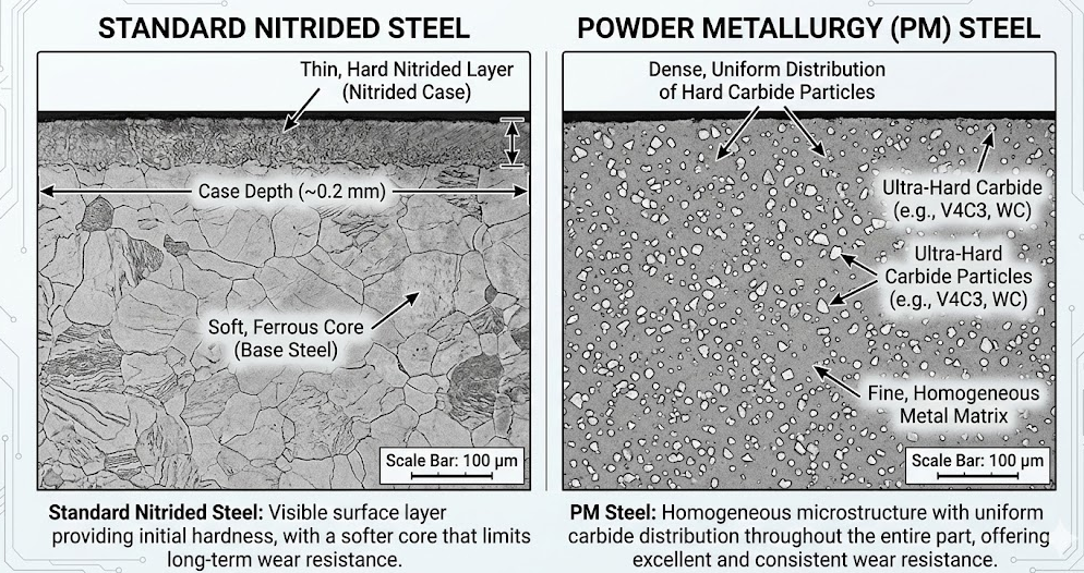
For the feed section—especially the first 2-3 elements downstream of the feed throat where compaction and wear are most brutal—we strongly recommend abandoning surface-nitrided materials. The nitrided layer is typically only 0.4–0.6mm thick. Once abrasive glass fibers breach this thin crust, the softer steel core is hollowed out in a matter of days.
Upgrading to a through-hardened High-Speed Steel, or for extreme conditions, Powder Metallurgy (PM) Tool Steel, provides a matrix packed with ultra-hard, uniformly distributed carbide particles. This acts as microscopic armor, delivering several times the lifespan of standard materials.
Real-World Factory Case Study: Extending Lifespan from 3 Months to 14 Months
Nothing speaks louder than actual production data. Here is a recent case study handled by our engineering team.
The Client: A North American automotive plastics supplier operating a 75mm twin-screw extruder to produce PA66 + 35% Glass Fiber composites.
The Pain Point: The client reported staggering wear rates in the compaction zone just past the feed throat due to the high GF loading and dry material nature. Every 3 months, the outer diameter of the flights wore down by over 1.5mm, choking the feed rate, dropping throughput by 20%, and forcing a shutdown for replacement.
Our Diagnosis & Solution:
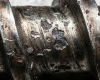
After analyzing the worn element photos and their screw profile, we identified an aggressive “cliff-drop” in their pitch transition, compounded by their use of standard D2 tool steel.
We engineered a targeted, cost-effective solution:
- Reconfigured the Screw Profile: We elongated the pitch gradient in the transition zone by introducing a non-standard 72/72 elongated pitch element as a buffer, drastically reducing the peak radial expansion pressure.
- Strategic Material Upgrade: We didn’t suggest upgrading the entire shaft, which would be cost-prohibitive. Instead, we applied a “right tool for the job” strategy. We precision CNC-machined only the three most severely stressed elements using premium high-vanadium Powder Metallurgy steel (SAM10 equivalent).
The Result:
Following the installation of our custom-machined parts, the extruder ran for over 14 continuous months before showing any minor throughput degradation. While the upfront cost of those specific PM parts was 40% higher, the client eliminated three costly maintenance shutdowns and massive labor costs, significantly boosting their overall annual profitability.
Conclusion: Let Precision Manufacturing Drive Your Efficiency
While feed section wear on a twin-screw extruder cannot be entirely eliminated, it absolutely should not act as a black hole draining your maintenance budget. By applying scientific flow geometry to eliminate abnormal compaction stress and deploying targeted, premium metallurgical materials, extending component life by 3x to 5x is a standard achievement.
We don’t just supply standard replacement parts; we engineer solutions to persistent manufacturing headaches.
Is your compounding line suffering from frequent wear and tear? Stop blindly replacing failing standard parts. Send us your current screw configuration diagrams or photos of your worn elements, along with your material formulation. Our engineering team will provide a comprehensive wear diagnosis and propose a custom-machined, high-ROI replacement strategy tailored to your specific process.
Frequently Asked Questions (FAQs)
1. How often should I inspect my twin-screw extruder feed elements?
For highly abrasive compounding (e.g., >30% glass fiber), we recommend pulling the screws and measuring the outer diameter (OD) and flight width every 3 to 4 months. For standard, lightly filled polymers, an annual inspection during scheduled preventive maintenance is usually sufficient. Keep a log of wear rates to predict replacement cycles accurately.
2. Can I use standard nitrided steel for glass-filled polymers?
We highly advise against it. Nitrided steel only has a hardened surface depth of about 0.4mm to 0.6mm. Glass fibers are highly abrasive and will quickly wear through this thin surface layer. Once the soft core is exposed, the element will degrade rapidly, leading to sudden drops in throughput and potential contamination.
3. What is the optimal clearance between the screw element and the barrel?
Optimal clearance depends on the diameter of your extruder. Generally, the radial clearance should be kept extremely tight—often around 0.15mm to 0.30mm for mid-sized extruders. If the clearance is too large, material slips backward over the flights, reducing efficiency and increasing shear wear. We manufacture our elements with tight tolerances to ensure minimal blow-by.
4. Why is material bridging happening in my feed throat, and how does it cause wear?
Bridging occurs when light powders or irregular regrind interlock and block the feed opening, preventing material from entering the screws. When the screws spin empty beneath a bridge, any trapped powder gets subjected to intense, localized friction without moving forward. This friction generates excessive heat and rapidly wears down the metal in that specific spot. Using undercut (SK) elements helps aggressively pull material down, preventing this issue.
5. Do I need to upgrade my entire screw shaft to premium powder metallurgy (PM) steel?
No, upgrading the entire shaft is usually not cost-effective. Wear in a twin-screw extruder is highly localized—typically concentrating in the compaction zone right after the feed throat and in the intensive melting/kneading blocks. We recommend a strategic approach: use premium PM-HIP steel only in these high-wear zones, and use standard tool steels or nitrided steels in the conveying and venting sections where wear is minimal.