If you spend enough time on the compounding shop floor, you quickly realize that while everyone loves to talk about optimizing screw element combinations, the barrel configuration often gets ignored.
In reality, the modular nature of a twin-screw extruder is only as good as the barrel layout and the machining precision behind it. At Jiangsu BLOOM, where we manufacture and customize extruder screw accessories, we’ve seen firsthand how a mismatched barrel setup—or poor tolerances—can ruin an otherwise solid process design.
Here is a practical look at how we approach barrel configuration, material selection, and troubleshooting for compounding applications.
01 Why Machining Precision Makes or Breaks the Setup
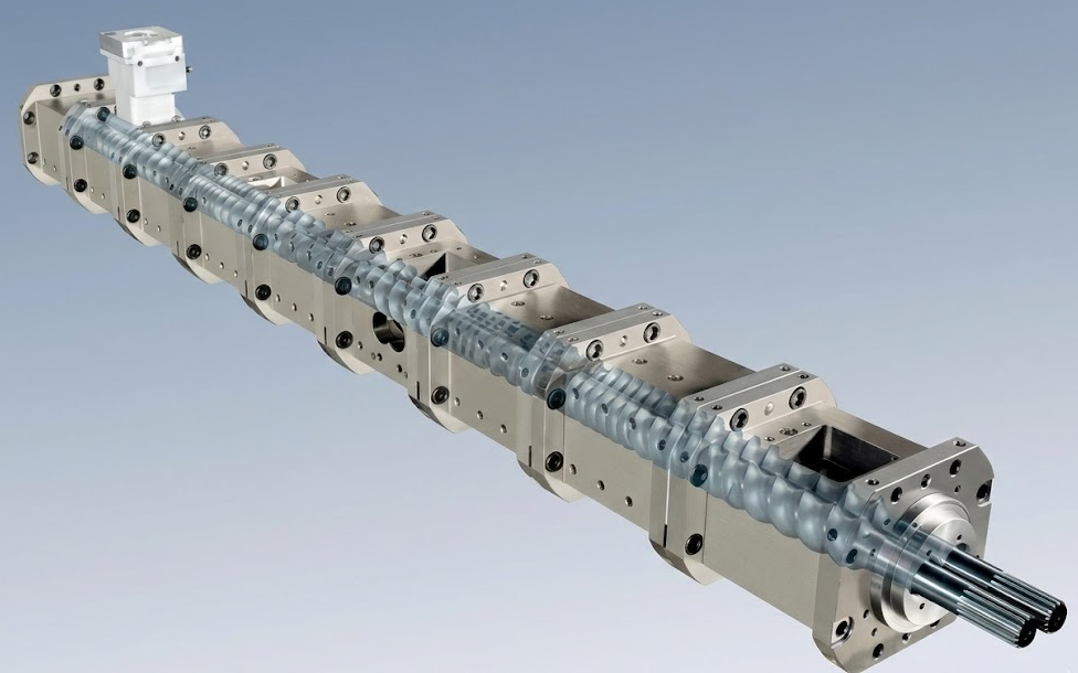
Most extruders use a segmented barrel design. This allows you to mix and match sections for feeding, melting, and venting based on the polymer and additives you are running.
But here is what often gets left out of the textbooks: tolerances matter just as much as the layout. When we machine replacement barrels and screw accessories, we typically hold the clearance between the barrel’s inner bore and the screw flight to a strict 0.15mm – 0.30mm, depending on the machine size. If this gap is uneven due to poor CNC machining, you get localized melt leakage, inconsistent shear, and eventually, the screw elements will rub against the barrel. A clever barrel configuration can’t fix bad machining.
02 Barrel Structures and Real-World Material Wear
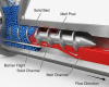
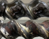
The “Figure-8” Bore
The standard twin-screw barrel has a “Figure-8” bore. The screws intermesh, forcing the plastic into a figure-8 flow path. This increases the residence time for better plasticization while preventing the material from just rotating with the screw.
Material Selection: What Actually Works?
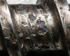
Over the years, we’ve seen customers burn through standard barrels in months because they ran high-glass-fiber compounds on the wrong steel. Here is a practical breakdown of what materials we recommend based on what you are actually compounding:
| Barrel / Liner Material | Manufacturing Note | Wear Resistance | Corrosion Resistance | When We Recommend It |
| Nitrided Steel (38CrMoAl) | Surface hardened. The hard layer is relatively shallow. | Fair | Fair | General purpose plastics, low-abrasion fillers. (Budget-friendly) |
| Bimetallic / High Chrome | Centrifugally cast or sintered. Much thicker wear layer. | Good | Good | Mid-range calcium carbonate or talc filled compounds. |
| CPM-10V Powder Metallurgy | High vanadium tool steel. Extremely dense. | Excellent | Good | High wear zones (like side feeders) or running 30%+ Glass Fiber. |
| Hastelloy / Nickel-based | Specialized alloy. Very expensive but necessary for acids. | Fair | Excellent | Fluoropolymers or highly corrosive flame retardants. |
Shop-Floor Tip: You don’t need to buy an entire CPM-10V barrel. We usually advise clients to just use replaceable CPM-10V liners in the highest wear zones, like the side-feed section. It saves money and downtime.
03 Practical Barrel Types
We generally work with two main categories of barrel sections:
- Open Barrels: These have external ports.
- Feed Barrels: Where the raw material drops in. If you run light, fluffy powders, we often set up a rear-venting barrel just behind the main feed to let trapped air escape, which stops the powder from bridging.
- Side-Feed Barrels: Located downstream once the resin is melted. We use these to introduce sensitive additives or fillers (like glass fiber) that shouldn’t go through the high-shear melting zone.
- Venting Barrels: Used for atmospheric or vacuum degassing.
- Closed Barrels: These have no openings. They enclose the melt completely and are used where you need tight temperature control for melting and mixing.
04 A Common Fix: 30% Glass Fiber (GF) PA66 Issues
To show how barrel configuration fixes real problems, let’s look at a common issue we help clients troubleshoot: glass fiber backing up at the side feeder and the vacuum port pulling out dry fibers.
- The Problem: The operator is adding GF too early. The side-feed barrel is too close to the vacuum vent, and they are using standard conveying elements under the feed port. The glass breaks, the melt doesn’t seal, and the vacuum pump gets clogged with glass dust.
- Our Solution:
- Move the Barrel: We push the side-feed barrel further downstream to ensure the PA66 is 100% melted and has low viscosity before the glass hits it.
- Element Swap: Directly under the side-feed barrel opening, we install large-pitch forward-conveying elements to yank the glass fiber forward quickly.
- Melt Seal Before Venting: Right before the vacuum barrel, we install reverse-pitch screw elements or reverse kneading blocks. This creates a physical “plug” of molten plastic. The vacuum can pull the gas out, but it can’t pull the heavy melt or the trapped fibers backward.
05 Maintenance Advice from the Supplier Side
You can have the best extruder in the world, but it will fail if you don’t maintain it. Here is what we tell our operators and clients:
- Check Your Clearances: Don’t wait for a drop in output to check your wear. Grab a caliper every few months and measure the barrel inner diameter and screw outer diameter in the melting section. Once that gap exceeds 0.8mm (for mid-sized machines), you are losing efficiency to backflow.
- Clean it Hot: If you are running a side feeder or a vent, clean the residual material out of the open barrel while the machine is still hot. If you let it cool and harden, it will scrape the barrel wall on the next startup or cause black specks in your next batch.
Barrel configuration isn’t just theory; it’s about matching the right steel and the right geometry to your daily production realities. Getting it right makes your process run smoother and your wear parts last much longer.