For plant managers, process engineers, and maintenance directors in the plastics, rubber, and food extrusion industries, the extruder screw is the beating heart of the production line. It is responsible for conveying, melting, mixing, and pumping the polymer matrix. However, operating under extreme pressures, high temperatures, and severe friction, it is also a highly vulnerable consumable component.
Premature screw wear leads to a cascade of operational inefficiencies: decreased throughput, inconsistent melt temperatures, surging, degraded mechanical properties in the final product, and ultimately, catastrophic downtime. According to data published by Plastics Technology magazine and supported by research from the Society of Plastics Engineers (SPE), worn screws and barrels can reduce processing capacity by 10% to 20% long before a catastrophic mechanical failure occurs. This silent degradation eats directly into profit margins, increasing energy consumption per kilogram of polymer processed and driving up scrap rates.
Extending the service life of your extruder screws is not merely a maintenance objective; it is a critical profitability strategy. This comprehensive guide provides an engineering-focused, data-driven approach to mitigating wear, optimizing metallurgy, and maximizing the operational lifespan of extrusion components.
Chapter 1: The Physics and Chemistry of Wear Mechanisms
Before implementing mechanical solutions, it is crucial to diagnose the specific degradation mechanisms attacking your equipment. Extruder screw wear is rarely caused by a single factor; it is usually a synergistic combination of three primary wear categories: abrasive, corrosive, and adhesive wear.
1.1 Abrasive Wear (Two-Body and Three-Body Abrasion)
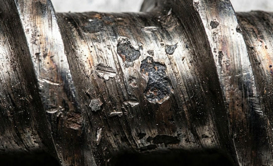
Abrasive wear is the most prevalent form of degradation in modern extrusion, driven by the increasing use of highly filled and engineered polymers. It occurs when hard particles within the polymer matrix scour the metallic surfaces of the screw flights and the root.
- Two-Body Abrasion: Occurs when rough, hard asperities on the barrel wall cut into the softer screw material (or vice versa).
- Three-Body Abrasion: This is the most common mechanism in plastics extrusion. Hard additives (the “third body”) are trapped between the screw flight land and the barrel wall. As the screw rotates, these particles act like microscopic cutting tools.
Common Culprits of Abrasive Wear:
- Glass Fibers: Used heavily in automotive and structural plastics (e.g., 30% to 50% glass-filled PA66). Glass has a high Mohs hardness and rapidly shears away standard steel.
- Mineral Fillers: Calcium carbonate ($CaCO_3$), talc, mica, and barium sulfate used to reduce resin costs or alter stiffness.
- Pigments and Additives: Titanium dioxide ($TiO_2$), often used for white pigmentation, is highly abrasive.
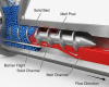
Abrasive wear typically manifests most aggressively in the transition (compression) zone of the screw, where the polymer is only partially melted, and the solid bed is tightly compressed against the barrel wall, forcing abrasive fillers into direct contact with the metal.
1.2 Corrosive Wear (Chemical Attack)
Corrosive wear is a chemical degradation process. It occurs when the polymer matrix, or its additives, break down at processing temperatures and release highly reactive, acidic byproducts. These acids attack the passive oxide layer of the screw steel, causing pitting, rust, and material dissolution.
High-Risk Corrosive Polymers:
- Polyvinyl Chloride (PVC): Both rigid and flexible PVC release hydrochloric acid (HCl) if localized shear heating causes the polymer to degrade.
- Fluoropolymers: Materials like PTFE, FEP, and PVDF require extremely high processing temperatures and release hydrofluoric acid (HF), which is notoriously destructive to standard steels.
- Flame Retardants: Halogenated flame retardants can release corrosive halides during processing.
Corrosive wear often acts as a catalyst for abrasive wear. The chemical attack softens the surface layer of the metal, creating micropits. Abrasive fillers then easily sweep away this weakened, oxidized layer, exposing fresh metal to further chemical attack in a rapid downward spiral.
1.3 Adhesive Wear (Galling)
Adhesive wear, commonly known as galling, is a catastrophic mechanical failure resulting from direct metal-to-metal contact between the screw flight outer diameter (OD) and the inner diameter (ID) of the barrel.
When the two metallic surfaces rub together under high pressure without the lubricating layer of molten polymer, localized friction generates intense heat. This heat causes micro-welds to form between the screw and barrel. As the screw continues to turn, these micro-welds are violently torn apart, ripping chunks of metal from the surfaces.
Causes of Adhesive Wear:
- Severe barrel or screw misalignment.
- Bowing of the screw due to excessive length-to-diameter (L/D) ratios combined with high head pressure.
- “Dry running” or operating the extruder without a sufficient polymer cushion (often occurring during startup or material starvation).
Chapter 2: Strategic Metallurgy and Surface Engineering
The foundation of screw longevity lies in the science of metallurgy. Using a “one-size-fits-all” standard steel screw for diverse polymer processing is a guaranteed path to premature failure. Material selection must be precisely matched to the wear mechanisms identified in Chapter 1.
2.1 Standard Nitriding: The Baseline
Historically, the industry standard has been to use medium-carbon alloy steels, such as AISI 4140 or 4340, treated with a gas or ion nitriding process. Nitriding diffuses nitrogen into the surface of the steel, creating a thin, hard case (typically 60-65 Rockwell C) that is about 0.010 to 0.015 inches deep.
- Pros: Cost-effective, suitable for unfilled, non-corrosive commodity resins like virgin LDPE or PP.
- Cons: Once the thin nitrided case is breached by abrasion, the softer core steel wears away exponentially faster. Nitriding offers virtually zero resistance to corrosive attack.
2.2 Bimetallic Hard-Facing: The Industry Workhorse
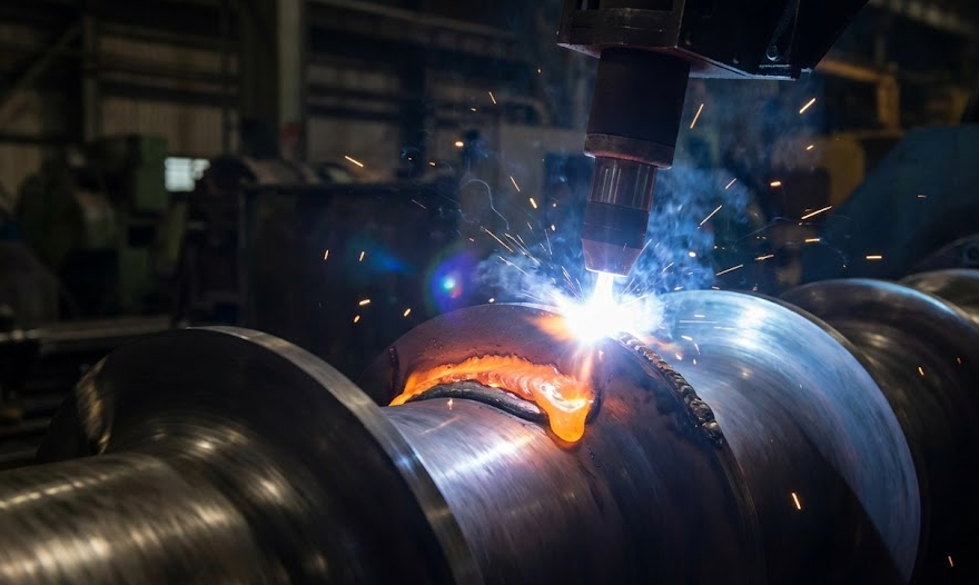
For environments subjected to moderate to severe abrasion, bimetallic hard-facing is critical. This process involves machining an under-cut into the top of the screw flight and welding a highly wear-resistant alloy into the groove using Plasma Transferred Arc (PTA) or Tungsten Inert Gas (TIG) welding.
Common Hard-Facing Alloys:
- Nickel-Chromium-Boron Alloys (e.g., Colmonoy 56): Provides excellent resistance to moderate abrasion and good corrosion resistance. Ideal for general-purpose high-performance screws.
- Tungsten Carbide Embedded Alloys: For severe abrasion (e.g., processing heavy glass-filled resins). Tungsten carbide particles are suspended in a nickel matrix. While the matrix may wear slightly, the extreme hardness of the carbide particles (often exceeding 70 Rc) absorbs the abrasive friction.
2.3 Through-Hardened Tool Steels
Instead of relying on a surface treatment or welded edge, high-performance screws can be machined entirely from premium tool steels.
- D2 Tool Steel: Offers a massive improvement in abrasive wear over nitrided 4140 due to its high chromium and carbon content, which forms massive wear-resistant carbides throughout the steel matrix.
- Powder Metallurgy (PM) Tool Steels (e.g., CPM 9V, CPM 10V): These represent the pinnacle of abrasive wear resistance. The powder metallurgy process ensures a highly uniform distribution of vanadium carbides, eliminating the structural weak points found in conventionally cast steels. If a PM tool steel flight wears down, the material underneath is exactly as hard as the surface.
2.4 High-Performance Coatings and Encapsulation for Corrosion
For extreme corrosive environments, hard-facing is insufficient because the corrosive gas will simply attack the root and flanks of the screw.
- Encapsulation: The entire wetted surface of the screw (root, flanks, and flights) is coated or machined from highly corrosion-resistant superalloys like Hastelloy C-276 or Inconel 625.
- Physical Vapor Deposition (PVD) / Chemical Vapor Deposition (CVD): Ultra-thin, exceptionally hard ceramic coatings like Chromium Nitride (CrN) or Titanium Nitride (TiN) can be applied to complex geometries. These coatings provide a highly lubricious, chemically inert barrier, though they are thin and can be compromised if abrasive wear is also present.
Chapter 3: Extrusion Process Parameters and Operational Best Practices
Even a screw machined from the most advanced aerospace-grade superalloy will fail prematurely if operated outside optimal parameters. Machine operators play the most critical role in extending component life.
3.1 The Danger of “Cold Starts”
Attempting to rotate the screw before the polymer inside the barrel has completely melted is a leading cause of catastrophic torsional failure and severe adhesive wear.
- The Soak Time Rule: Reaching the setpoint temperature on your HMI controller does not mean the polymer mass is melted. The thermocouple only measures the barrel wall temperature. Depending on machine size, operators must enforce a mandatory “soak time” (often 30 to 120 minutes) after setpoints are reached to allow thermal conduction to penetrate the core of the polymer bed.
- Monitoring Motor Load: Upon startup, motor amperage should be monitored closely. If the amperage spikes abnormally high, the material is not fully plasticized. Stop rotation immediately to prevent shearing the screw shank.
3.2 Temperature Profiling and Shear Heat Management
Extrusion is a delicate balance of conducted heat (from heater bands) and generated heat (mechanical shear from the screw).
- Reverse Temperature Profiles: In high-shear applications, excessive heat generation in the transition zone can degrade the polymer and increase wear. Utilizing a reverse temperature profile (higher heat in the feed zone, lower in the metering zone) can sometimes delay the onset of melting, shifting the high-pressure grinding away from the delicate transition flights.
- Screw Cooling: For materials highly sensitive to shear, implementing internal screw cooling (circulating water or oil through the bore of the screw) can control melt temperature, but it must be managed carefully. Over-cooling the screw can cause the polymer to freeze onto the root, effectively changing the screw geometry and reducing throughput.
3.3 Screen Pack and Breaker Plate Management
The screen pack is designed to filter out contaminants and create necessary backpressure to ensure proper mixing. However, poor screen management is a silent killer of extruder screws.
- Excessive Backpressure: As screens blind (clog) with contaminants, head pressure rises exponentially. High head pressure forces the screw backward with immense force against the thrust bearing.
- Axial Deflection: Furthermore, high pressure in the die area forces the polymer to seek the path of least resistance—leaking backward over the screw flights. This high-velocity leakage is highly abrasive and accelerates wear on the outer diameter of the metering zone flights. Implement continuous screen changers or establish strict pressure thresholds for manual screen changes.
Chapter 4: The Synergistic Relationship: Screw and Barrel
An extruder screw does not operate in a vacuum; it is half of a dynamic system. You cannot maximize screw life without equally addressing the condition of the barrel.
4.1 Barrel Alignment and Support
A misaligned barrel will force the screw to bend with every rotation. This cyclic fatigue causes two problems:
- Adhesive Wear: The bowed screw constantly rubs against one side of the barrel, wiping away the polymer cushion and causing metal-to-metal galling.
- Fatigue Failure: The continuous bending creates microscopic fatigue cracks in the root of the screw, usually in the feed section where the root diameter is smallest. Over time, this leads to the screw snapping cleanly in half.
Solution: Laser alignment of the gearbox, feed throat, and barrel should be a mandatory annual preventative maintenance task, especially after any major maintenance involving moving the extruder base.
4.2 Matching Wear Profiles
Installing a brand-new, high-performance tool steel screw into a severely worn, barrel is a waste of capital.
If the barrel is worn (meaning the inner diameter has increased), the clearance between the new screw flight and the barrel wall will be too large. This excessive clearance reduces pumping efficiency, increases shear heat, and can actually cause the new screw to bounce or deflect inside the barrel, damaging the new flights.
- Rule of Thumb: Always measure both the screw and the barrel simultaneously. If barrel wear exceeds accepted tolerances, it must be relined or replaced concurrently with the screw.
Chapter 5: In-Depth Industry Case Studies
To understand the practical application of these engineering principles, consider the following real-world scenarios handled by leading extrusion manufacturers.
Case Study 1: Combating Severe Abrasion in Infrastructure Pipe Manufacturing
The Challenge: A facility manufacturing large-diameter, high-density polyethylene (HDPE) corrugated pipes for municipal water infrastructure was utilizing a 30% recycled glass-fiber fill to increase the ring stiffness of their pipes. They were utilizing standard OEM nitrided screws (AISI 4140).
The highly abrasive glass fibers were violently scouring the transition zone of the screws. The factory was experiencing a 15% drop in output capacity every three months due to lost pumping efficiency, and they were forced to perform full screw replacements three times a year per extrusion line.
The Solution: The plant’s mechanical engineering team partnered with a specialized component manufacturer to completely redesign the wear profile. The solution involved a three-tiered approach:
- Material Upgrade: The base material of the screw was upgraded from 4140 steel to CPM 9V, a powder metallurgy tool steel offering exceptional through-hardness.
- Bimetallic Hard-Facing: To protect the critical flight ODs, a Colmonoy 56 (Nickel-Chromium-Boron) bimetallic hard-facing was welded onto the lands.
- Geometric Redesign: The compression ratio was slightly relaxed to reduce the pressure peaks and shear heat in the transition zone, smoothing the melting process and reducing the grinding force against the barrel wall.
The Result: The upgraded bimetallic tool-steel screw ran for 14 uninterrupted months before reaching the critical wear tolerance—a staggering 366% increase in service life. While the initial capital expenditure for the custom screw was 40% higher than the standard nitrided version, the massive reduction in machine downtime, maintenance labor, and replacement parts resulted in an estimated, audited annual savings of $45,000 per extrusion line.
Case Study 2: Conquering Chemical Attack in Medical Tubing
The Challenge:
A cleanroom facility extruding precise medical catheters was processing Fluorinated Ethylene Propylene (FEP). While FEP is not abrasive, it requires processing temperatures exceeding 350°C (662°F). At these temperatures, FEP outgasses trace amounts of hydrofluoric acid.
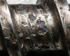
The standard bimetallic screws were suffering from severe corrosive pitting in the root. This pitting created “dead zones” where the polymer would hang up, degrade, and create black specks in the clear medical tubing, leading to a 22% scrap rate.
The Solution:
Because the wear was purely chemical and attacking the entire geometry (not just the flights), standard hard-facing was useless. The engineers specified a custom screw machined entirely from solid Hastelloy C-276, a nickel-molybdenum-chromium superalloy with the addition of tungsten, renowned for its supreme resistance to severe chemical environments.
The Result:
The Hastelloy screw eliminated the surface pitting entirely. Polymer flow dynamics were stabilized, the “black speck” contamination was eradicated, and the scrap rate dropped from 22% to an industry-leading 1.5%. The screw paid for itself in reduced scrap material within the first 45 days of operation.
Chapter 6: Implementing a Proactive Maintenance Protocol
Reactive maintenance—waiting for the extruder to lose output before checking the screw—is an expensive operational flaw. A world-class extrusion facility relies on proactive, predictive maintenance.
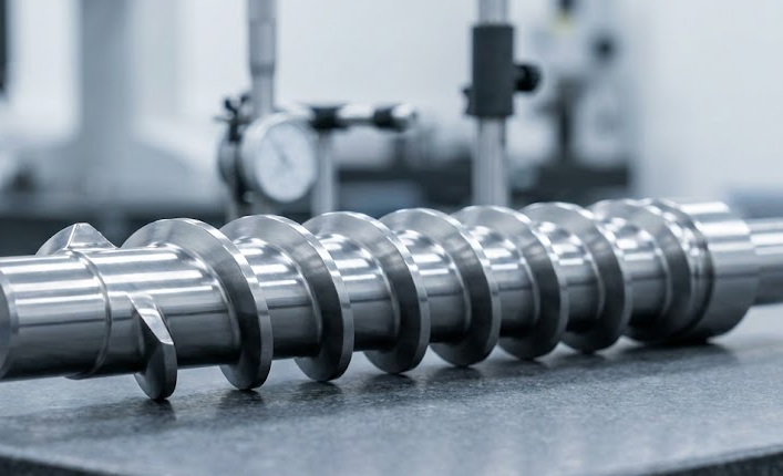
6.1 Establish a Measurement Baseline
You cannot manage what you do not measure. Every new screw and barrel must be measured before installation. Do not blindly trust the OEM drawings; verify the exact Outer Diameter (OD) of every flight and the Inner Diameter (ID) of the barrel at multiple zones. Record these baseline measurements in a dedicated equipment log.
6.2 Scheduled Pulls and Micrometer Inspections
Establish a schedule to pull, clean, and measure your screws periodically. For highly abrasive applications, this might be every three months; for benign applications, annually.
- Use a calibrated outside micrometer to measure the flight OD at the same specific locations each time.
- Calculate the exact clearance between the screw OD and the barrel ID. As a general rule in the plastics industry, once the radial clearance exceeds 0.002 inches per inch of screw diameter (e.g., a total clearance of 0.012″ on a 6-inch screw), pumping efficiency will drop noticeably, and shear heat will increase. Documenting these wear rates allows you to predict end-of-life and order custom replacements months before catastrophic failure occurs.
6.3 Proper Purging Procedures
How you shut down the machine dictates the wear it experiences upon the next startup.
- Never leave degradable polymers in a hot barrel. Materials like PVC, Acetal, or EVOH will quickly carbonize if left at processing temperatures without rotation. Carbonized polymer acts like diamond grit. When the machine is restarted, this hard carbon violently scours the screw and barrel.
Use Commercial Purging Compounds: Invest in chemical or mechanical purging compounds designed specifically for your resins. When shutting down for the weekend, displace the production resin with a thermally stable purging compound. This protects the metallic surfaces from oxidation and ensures a smooth, low-torque startup.