A few years back, a pipe manufacturer in Southeast Asia reached out to us at BLOOM with a familiar problem: their output had dropped nearly 30% after switching resin suppliers, and energy costs were climbing. The machine hadn’t changed. The operator hadn’t changed. The only variable was a slightly different melt index on their HDPE grade — but their screw hadn’t been designed to handle it.
That’s the reality of extruder screw selection for PE and PP: the details matter enormously. These two polyolefins account for over 40% of global plastic production, yet choosing the wrong screw geometry, compression ratio, or surface treatment can quietly erode your output, quality, and profit margin every single shift.
In this guide, we’ll walk through the core principles and real technical parameters that define a well-matched PE or PP extruder screw — from L/D ratios and compression design to material choices and barrier technology. Whether you’re speccing a new line or troubleshooting an existing one, the information here is grounded in what actually works on the factory floor.
What Makes PE and PP Different — and Why Your Screw Must Match
The Physical Properties That Drive Screw Design
Polyethylene (PE) and polypropylene (PP) are both semi-crystalline polyolefins, but they’re not interchangeable from a processing standpoint. PE variants range from low-density (LDPE, melt index 0.3–20 g/10min) to high-density (HDPE, melt index 0.1–5 g/10min), each demanding different shear sensitivity and cooling profiles. PP runs hotter and has a sharper melting transition, typically processing between 195°C and 240°C, while PE sits in the 170°C–230°C window depending on grade.
These differences translate directly into screw geometry requirements: the length of the transition zone, the channel depth ratio, and the flight pitch all need to be tuned to the specific polymer’s melt behavior — not just the broad category of “polyolefin.”
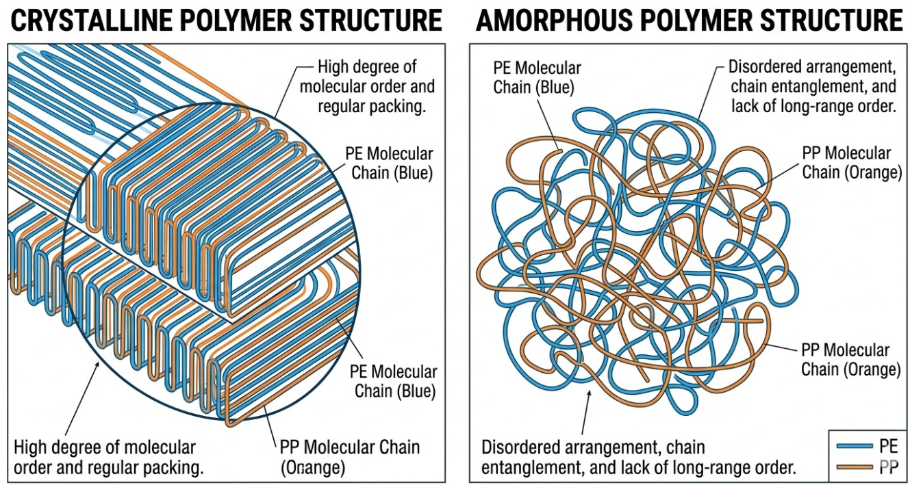
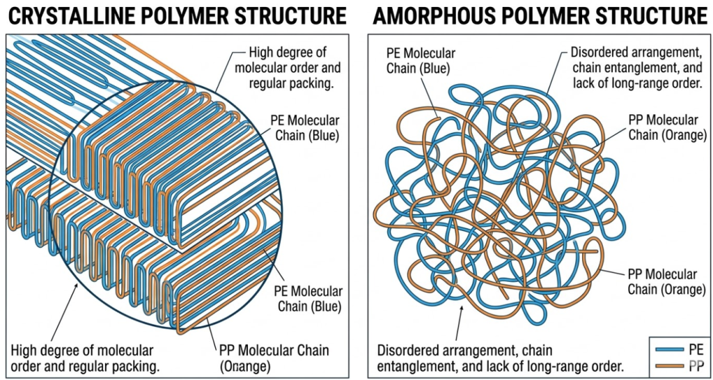
Crystalline Polymers: Why the Melting Zone Is Critical
Both PE and PP are crystalline materials, meaning they don’t gradually soften like amorphous plastics (ABS, PC). Instead, they hold their solid structure until a defined melting point, then transition relatively quickly. This demands a screw with a short, aggressive compression zone that delivers the mechanical and thermal energy in a concentrated region — rather than the long, gradual transition you’d use for something like polystyrene.
Get the compression zone wrong — too long, too short, too shallow — and you either get unmelted pellets passing into the metering zone, or excessive shear heat that degrades the polymer. Neither outcome is visible until you’re already making reject product.
Key Technical Parameters for PE & PP Extruder Screw Selection
L/D Ratio — The Foundation of Screw Length
The L/D (length-to-diameter) ratio is one of the first specifications any engineer should nail down. For PE and PP processing, the standard starting point is 24:1, but the right value depends heavily on your application. Pipe extrusion, which demands thorough homogenization and pressure consistency, typically benefits from L/D values of 28:1 to 30:1. Recycling lines, where shorter residence time reduces thermal history, can often work well at 20:1 to 24:1.
A longer screw doesn’t automatically mean better quality — it means more time for melting, mixing, and pressure development. For straightforward PE/PP pellet-fed applications, going beyond 30:1 often yields diminishing returns while increasing energy consumption and mechanical stress on the drive system.
Table 1 — L/D Ratio Recommendations by Application
| Application | Recommended L/D | Key Reason |
|---|---|---|
| PE pipe extrusion | 28:1 – 30:1 | Needs thorough melting & pressure stability |
| PP film extrusion | 25:1 – 30:1 | Precise melt temperature control critical |
| PE/PP recycling pelletizing | 20:1 – 24:1 | Shorter residence time reduces degradation |
| HDPE blow molding | 24:1 – 28:1 | Balanced output vs. melt quality |
| PP injection compounding | 28:1 – 32:1 | Extended mixing for filled materials |
| General purpose PE/PP | 24:1 | Industry-standard starting point |
Compression Ratio — Matching the Polymer’s Melt Behavior
Compression ratio describes the relationship between the channel depth in the feed zone and the channel depth in the metering zone — typically expressed as a simple ratio like 3:1. For crystalline polymers like HDPE and PP, a compression ratio in the range of 3:1 to 3.5:1 is generally appropriate. LDPE, being softer and more shear-sensitive, often performs better at the higher end: 3.5:1.
Recycled PE/PP streams present a different challenge. Contamination, varying bulk density, and inconsistent melt index mean a slightly lower compression ratio (2.5:1 to 3:1) often provides more stable processing, especially when paired with a vented screw design to remove moisture and volatiles.
Table 2 — Processing Parameters for PE & PP Variants
| Material | Compression Ratio | Cylinder Temp (°C) | Melt Temp (°C) | Recommended Screw Type |
|---|---|---|---|---|
| HDPE | 3:1 | 180–205°C | 180–205°C | Barrier Screw |
| LDPE | 3.5:1 | 170–200°C | 170–200°C | Barrier Screw |
| LLDPE | 3:1 | 180–210°C | 190–210°C | Barrier / Standard |
| PP Homopolymer | 3:1 – 3.5:1 | 195–240°C | 200–240°C | Standard / Barrier |
| PP Copolymer | 3:1 | 190–230°C | 195–230°C | Standard Screw |
| Recycled PE/PP | 2.5:1 – 3:1 | 170–220°C | 180–215°C | Vented Screw |
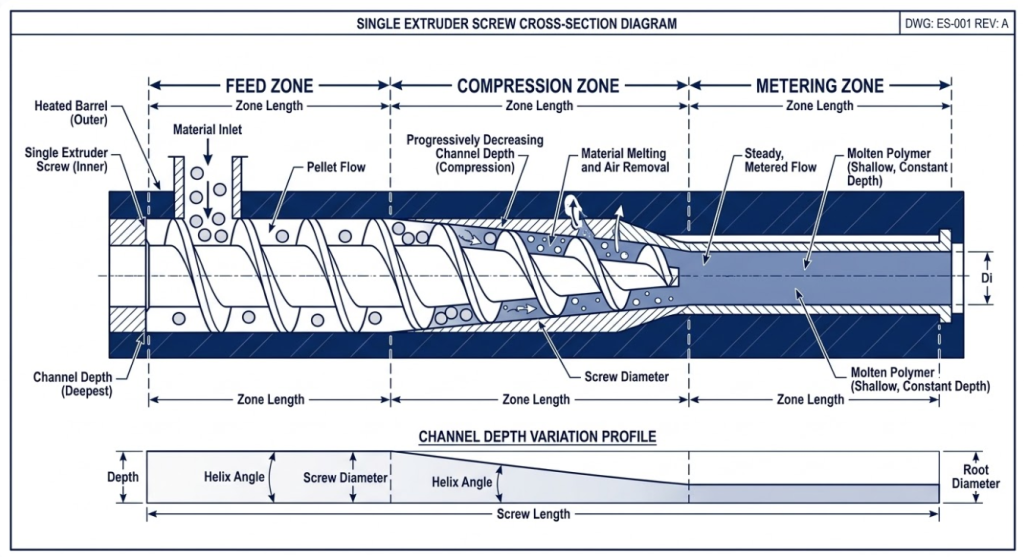
Three-Zone Design — Feed, Compression, Metering Explained
Every standard single-screw extruder screw passes material through three functional zones. The feed zone has deep, constant-pitch channels that convey solid pellets forward while applying initial frictional heat. The compression zone (also called the transition zone) gradually reduces channel depth, mechanically compressing the material and finishing the melting process. The metering zone has shallow, consistent channels that build pressure and homogenize the melt before it reaches the die.
For PE processing, a typical zone distribution might be 50-30-20 (feed-compression-metering as a percentage of total screw length). PP, with its sharper melting transition, sometimes benefits from a shorter compression zone — around 25% — to concentrate the energy delivery and avoid burning the resin in the transition region.
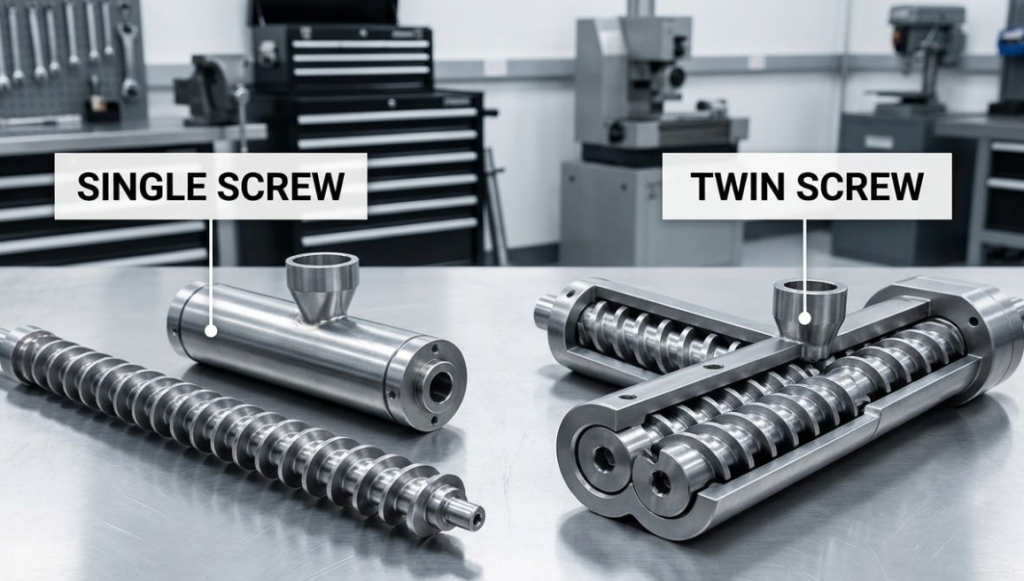
Single Screw vs. Twin Screw — Which One for PE and PP?
This is one of the most common questions we get at BLOOM, and the honest answer is: it depends on what you’re doing with the material, not just what material you’re running.
Single-screw extruders handle the majority of PE and PP applications — pipe, film, sheet, blow molding, monofilament — because these processes primarily need consistent melt delivery with moderate mixing. The screw design is simpler, the machines cost less, and maintenance is straightforward. For commodity PE/PP pellet processing, a well-designed single screw with a barrier flight outperforms a twin screw on cost-per-kilogram output every time.
Twin-screw systems earn their place when the process requires intensive distributive mixing, handling of powders or difficult feed materials, reactive extrusion, or compounding with fillers and additives. If you’re producing glass-fiber reinforced PP, carbon black masterbatch, or processing regrind with high volatiles content, a co-rotating twin screw is almost certainly the right tool.
Table 3 — Single Screw vs. Twin Screw for PE/PP Processing
| Feature | Single Screw | Twin Screw (Co-rotating) |
|---|---|---|
| Best applications | Pipe, film, sheet, blow molding | Compounding, masterbatch, recycling |
| Typical output range | Up to ~500 kg/h | Up to 2,000+ kg/h |
| Distributive mixing | Basic | Excellent |
| Dispersive mixing | Moderate (with mixing elements) | Very high |
| Powder feeding (PE/PP) | Limited — bridging risk | Excellent |
| Pellet feeding | Excellent | Good |
| Equipment cost | Lower | Significantly higher |
| Maintenance complexity | Simple | More complex (wear on elements) |
| Energy consumption | Lower per kg | Higher per kg |
| Devolatilization | Possible with vented design | Excellent (multiple vent ports) |
Screw Material & Surface Treatment — What Actually Lasts
Common Screw Steel Grades for PE/PP Applications
The base material of your extruder screw has a direct impact on service life, especially when processing filled or recycled PE/PP grades. The most widely used steel for standard PE/PP processing is 38CrMoAlA — a chrome-molybdenum-aluminum alloy steel that nitriding responds to extremely well. After gas nitriding, surface hardness reaches HRC 65–70 with a case depth of 0.4–0.7mm. It’s the workhorse of the industry for good reason: it balances cost, machinability, and performance effectively.
For demanding applications — processing glass-fiber reinforced PP or highly filled PE compounds — W6Mo5Cr4V2 (M2 high-speed steel) or bimetallic construction becomes the right choice. Bimetallic screws use a base of 42CrMo alloy steel with an inlaid alloy layer of 1–2mm thickness, delivering surface hardness of HRC 60–65 with superior abrasion resistance.
Nitriding vs. Bimetallic — Making the Right Call
The choice between nitrided and bimetallic depends on what’s in your melt. If you’re running clean, unfilled PE or PP homopolymer, a properly nitrided 38CrMoAlA screw will give you years of reliable service. If your compound contains calcium carbonate at 20%+ loading, glass fibers, mineral fillers, or recycled content with abrasive contaminants, a bimetallic screw will pay for itself quickly in reduced downtime and replacement cycles.
At BLOOM, our bimetallic screws consistently demonstrate service life 2–3× longer than standard nitrided equivalents in abrasive compound applications. The alloy layer composition — typically a nickel-based or iron-based matrix with tungsten carbide particles — is selected based on the specific abrasive agent in the compound, not just applied generically.
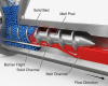
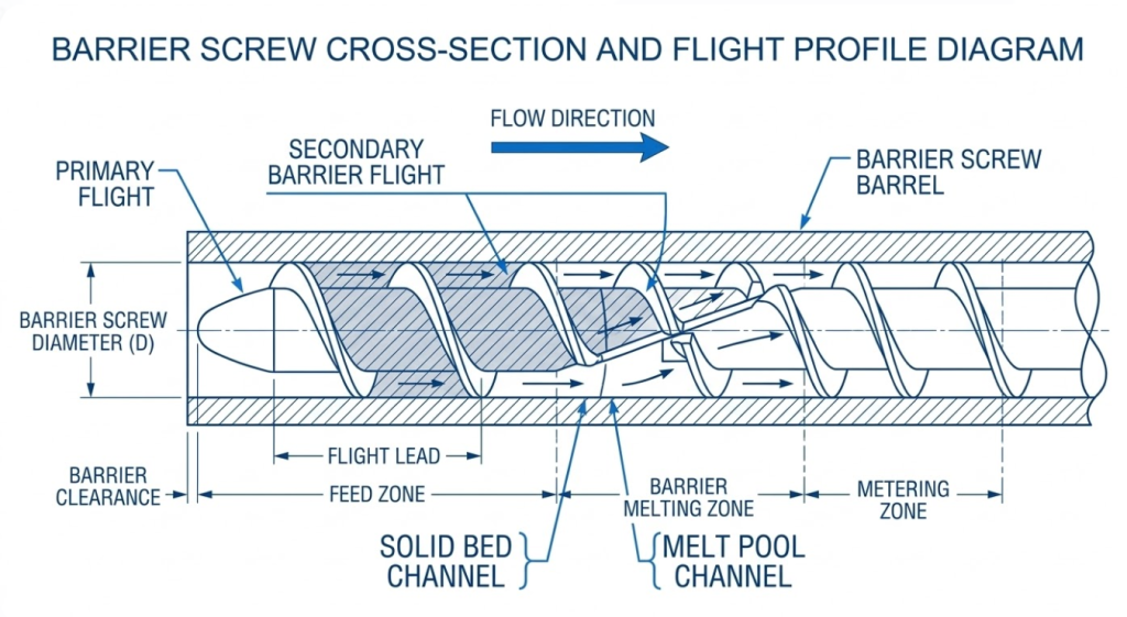
Barrier Screw Design — The Preferred Choice for PE & PP
If you’re processing HDPE, LDPE, or LLDPE at any meaningful volume, you’ve probably encountered the barrier screw — and with good reason. The barrier flight design addresses the single biggest limitation of conventional three-zone screws: the mixing of solid and molten material in the melting zone, which leads to inconsistent melt temperature, higher energy consumption, and pressure fluctuations at the die.
A barrier screw adds a secondary flight in the compression zone that physically separates the unmelted solid bed from the growing melt pool. Solid material stays in the primary channel until it melts, then passes over the barrier flight into the melt channel. The result is a more controlled, more consistent melting process — and in practice, output rates can increase 10–20% with the same drive power compared to a conventional screw on the same HDPE compound.
Key design parameters for a PE barrier screw: the barrier flight clearance is typically 0.8–1.5× the primary flight clearance, the barrier helix angle is usually set 2–5° less than the primary flight, and the overall compression ratio of 2.5:1 to 4:1 distributes across both the primary and barrier channels in a calculated sequence rather than a simple taper.
BLOOM Application Note: One of our clients running a 90mm HDPE pipe extrusion line reported a 15% throughput increase after switching from a standard three-zone screw (L/D 24:1) to a BLOOM barrier design (L/D 28:1) — without any changes to the barrel temperatures, die tooling, or haul-off settings. The primary improvement was melt temperature consistency, which reduced gel formation and allowed them to increase line speed without quality issues.
How BLOOM Customizes Extruder Screws for Your PE/PP Process
BLOOM has been manufacturing precision extruder screws and barrels for over 20 years, supplying customers across the pipe, film, packaging, compounding, and recycling sectors. Our production facility runs CNC turning centers, deep-hole drilling equipment, nitriding furnaces, and bimetallic casting lines under one roof — which means we control every step of the manufacturing process rather than outsourcing critical operations.
Our custom screw process starts with your application data: resin grade and MFI, output target (kg/h), machine make and model, current screw geometry if available, and any specific quality requirements (melt temperature tolerance, pressure consistency, etc.). From there, our engineering team proposes a screw design with full parameter documentation before production begins.
We also offer reverse engineering for worn or damaged screws where original drawings are unavailable — a common situation for older imported lines. Delivery lead time for standard designs is typically 15–20 working days; complex bimetallic or multi-zone designs run 25–35 days. OEM and ODM supply programs are available for distributors and machine manufacturers requiring consistent supply with branded or unbranded finish.
Common Mistakes When Choosing a PE/PP Extruder Screw
After two decades of troubleshooting calls from customers around the world, here are the mistakes we see most often — and what to do instead:
- Using a general-purpose screw for HDPE. General-purpose screws have lower compression ratios and longer transition zones that work adequately across many materials — but HDPE wants aggressive compression and short transitions. The result is usually lower output, higher melt temperature variance, and unexpected pressure spikes. Specify a screw designed for HDPE or use a well-designed barrier geometry.
- Choosing too low a compression ratio for PP. PP has a defined crystalline melting point and doesn’t forgive a screw that can’t deliver the right compression energy. Under-compressed PP comes through the metering zone partly solid, creating unmolten “eyes” in film or surface streaks in pipe. Minimum compression ratio for PP homopolymer: 3:1.
- Ignoring the abrasive content when specifying surface treatment. Running glass-filled PP through a nitrided screw that was specced for unfilled resin is a common and expensive mistake. Bimetallic or tungsten carbide-tipped screws aren’t a luxury for abrasive compounds — they’re the economical choice once you factor in replacement frequency.
- Selecting an L/D ratio that’s too short. A 20:1 screw on a demanding HDPE pipe application will never build the pressure consistency needed for close-tolerance wall thickness. It’s not a settings problem — it’s a geometry problem. Always match L/D to the specific output and quality requirements of the application.
- Ignoring screw-to-barrel clearance on worn equipment. When the diametral clearance between screw flight OD and barrel bore exceeds 0.15–0.20mm, you start to lose output efficiency and melt consistency regardless of screw design. On older machines, measure the barrel bore before ordering a new screw — you may need to refurbish or reline the barrel at the same time.
Frequently Asked Questions
Q1: What is the best L/D ratio for a PE extruder screw?
For most PE applications — pipe, film, and sheet — an L/D ratio of 25:1 to 30:1 is the right range. HDPE in particular benefits from the longer residence time a 28:1 or 30:1 screw provides, as this allows more complete and consistent melting. For simpler pelletizing or recycling applications, 20:1 to 24:1 is usually sufficient. At BLOOM, we always calculate L/D in the context of your target output rate and melt quality requirements — there’s no single “best” value without that context.
Q2: Can I use the same extruder screw for both PE and PP?
Technically yes — many processors run a general-purpose screw on both. But you’ll be compromising performance on at least one of them. PE and PP differ in processing temperature, viscosity profile, and crystallization behavior in ways that matter for screw design. If you’re primarily running one resin and occasionally the other, optimize for your main material. If you’re running both regularly, consider whether a slight performance compromise is acceptable, or whether two dedicated screws make more economic sense over a full production year.
Q3: What compression ratio should I choose for PP processing?
PP homopolymer generally works best with a compression ratio of 3:1 to 3.5:1. PP copolymers and impact grades often run well at 3:1. The key is matching the compression energy to the resin’s crystalline melting point — PP has a sharper melting transition than LDPE, so a slightly more aggressive ratio helps ensure complete melting without relying on excessive shear heat. Running PP at too low a compression ratio is a common cause of plastication problems and surface defects.
Q4: What is the difference between a nitrided and a bimetallic screw for PE/PP?
A nitrided screw (38CrMoAlA base steel, gas nitrided) offers surface hardness of HRC 65–70 with a case depth of 0.4–0.7mm. It’s the right choice for unfilled or lightly filled PE/PP processing and represents good value for standard applications. A bimetallic screw uses a 42CrMo base with a 1–2mm inlaid alloy layer — typically nickel- or iron-based with carbide particles — delivering hardness of HRC 60–65 with dramatically higher abrasion resistance. For compounds with mineral fillers, glass fiber, or high recycled content, bimetallic screws from BLOOM typically last 2–3 times longer, which more than offsets the higher initial cost.
Q5: How do I know when my PE/PP extruder screw needs replacement?
The clearest indicators are: inconsistent output pressure at constant screw speed; gel spots, streaks, or unmelted particles in your product; unexplained drops in throughput; and increased specific energy consumption (kWh per kg). Physically, if the diametral clearance between the screw flight OD and barrel bore exceeds 0.15–0.20mm, you’re losing efficiency. BLOOM offers screw measurement and inspection services — send us your screw and we’ll assess wear, check geometry against original spec, and recommend repair, refurbishment, or replacement depending on the condition.