The Engineer’s Guide to Solving Cable Insulation Eccentricity at the Source
I’ve spent the better part of two decades walking plant floors and troubleshooting wire and cable lines. If there is one thing I see operators constantly fighting, it’s the centering bolts on the crosshead die. When a cable fails a spark test or a dimensional check due to insulation eccentricity and uneven wall thickness, the instinct is always to blame the tooling. But in the highly demanding field of wire coating, achieving perfect concentricity is about more than just die alignment; it requires absolute consistency in polymer melt delivery. At BLOOM, our engineering data shows that the root cause of these defects almost always traces back to the barrel. Upgrading to a precisely engineered custom extruder screw stabilizes melt pressure, guarantees thermal homogeneity, and eliminates eccentricity before the plastic even reaches the die. This guide breaks down the mechanics of why standard screws fail at high speeds and how tailored geometries—like barrier flights and specialized mixing sections—can lock in your tolerances. If you’re dealing with broader line issues, you can also check out our Guide to Extrusion Line Troubleshooting for more practical fixes.
Stop Blaming the Crosshead: The Physics of Insulation Eccentricity
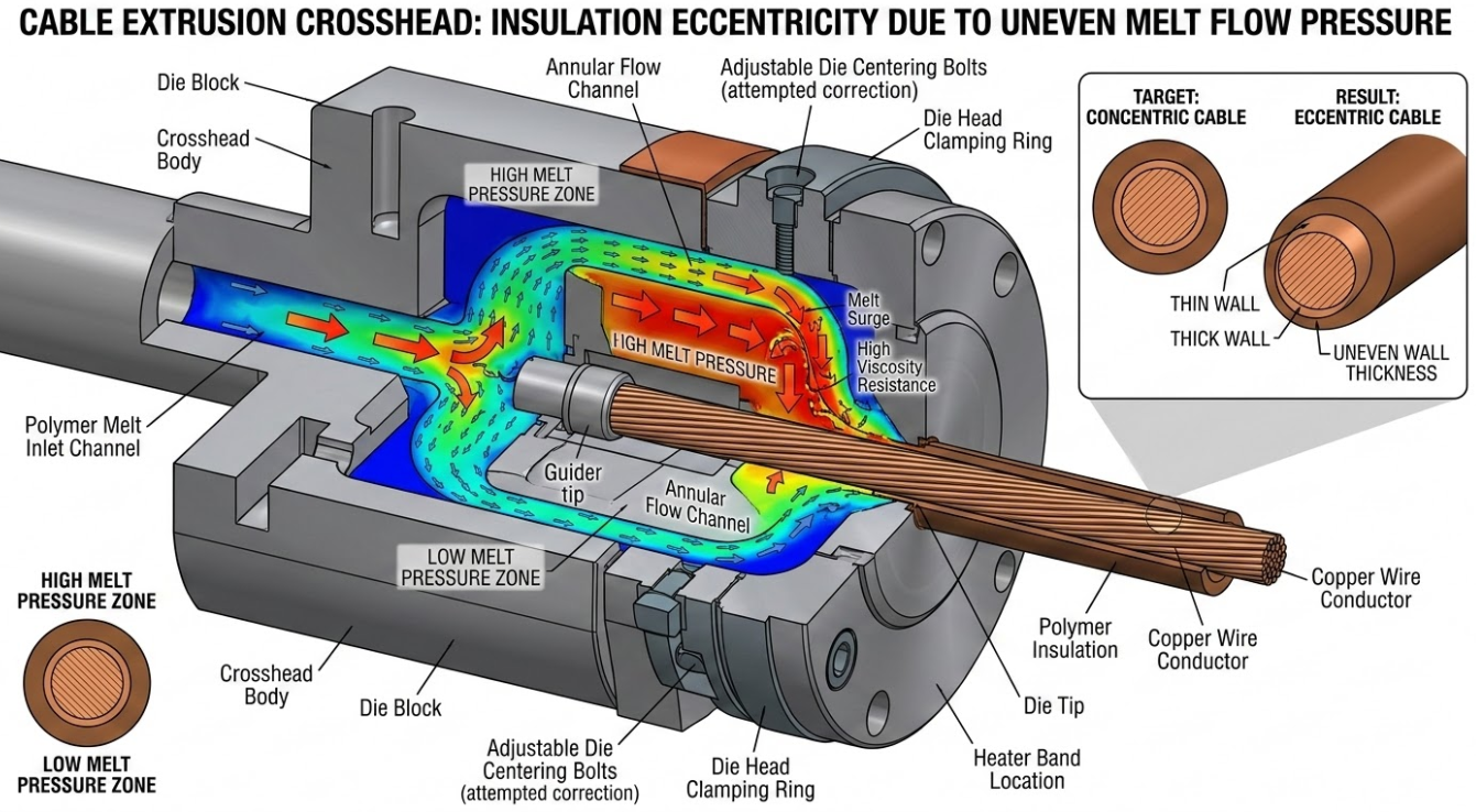
Let’s talk about what actually happens inside the barrel. Insulation eccentricity occurs when the copper or aluminum conductor is pushed off-center inside the polymer matrix. Operators will tweak the die head to compensate, but if the issue is dynamic—meaning the thin spot moves around the circumference of the cable or pulses down the length of the wire—tooling adjustments are useless.
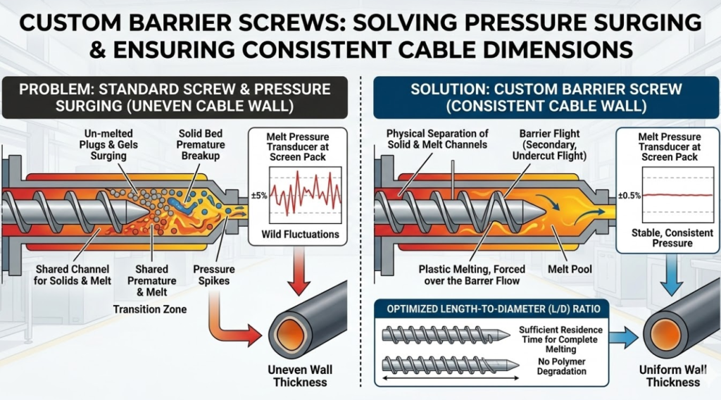
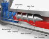
Comparison showing how a custom extruder screw with barrier technology prevents melt pressure surging and uneven cable insulation.
This dynamic shift is caused by pressure surging (pulsation) and uneven melt temperatures. If the polymer melt entering the crosshead isn’t 100% thermally homogenous, you have viscosity variations. Polymer flows through the path of least resistance. If one side of the melt stream is 5 degrees hotter (and therefore less viscous) than the other, the melt will flow faster on that side, physically shoving the tense conductor wire off-center. A standard, off-the-shelf single-flight screw simply cannot maintain the strict tolerances required for modern, high-speed wire coating, especially as barrel clearance increases with wear.

Eliminating Pressure Surging with a Custom Extruder Screw Design
Pressure surging is the enemy of consistent wall thickness. If your melt pressure transducer is swinging by more than ±1% at the screen pack, your cable dimensions are fluctuating. On a standard screw, the solid pellets and the molten polymer share the same channel in the transition zone. At high RPMs, the solid bed can break up prematurely, sending un-melted “plugs” or gels surging forward, which violently spikes the pressure.
We solve this by designing custom barrier screws. A barrier flight is a secondary, undercut flight introduced in the transition zone that physically separates the solid channel from the melt channel. As the plastic melts, it is forced over the barrier flight into the melt pool. This ensures that only fully plasticized material can move forward to the metering section. Furthermore, optimizing the Length-to-Diameter (L/D) ratio based on the specific resin ensures you have enough barrel residence time to melt the polymer without degrading it.
Table 1: Parameter Comparison – Standard Single-Flight vs. BLOOM Custom Barrier Screw
| Parameter | Standard Single-Flight Screw | BLOOM Custom Barrier Screw | Impact on Cable Insulation Quality |
| Solid/Melt Separation | Mixed phases in one channel | Physical barrier separation | Prevents un-melted gels from causing sudden thickness spikes. |
| Pressure Stability | High fluctuation (±5% or more) | Highly stable (±1%) | Eliminates pressure surging, maintaining perfect wire concentricity. |
| Output Rate (kg/hr) | Plateaus at higher RPMs | 15-25% higher output | Allows for faster line speeds without compromising wall thickness. |
| Shear Heat Control | Inconsistent, risks burning | Precisely engineered | Prevents thermal degradation, crucial for sensitive LSZH compounds. |
Thermal Homogeneity: Why a Custom Extruder Screw Outperforms Standard Designs
You cannot extrude what you haven’t properly melted, and you certainly can’t coat a wire evenly if your melt has cold spots. The compression ratio (the volume of the feed flight divided by the volume of the metering flight) dictates how much shear heat is mechanically introduced into the material.
Standard screws try to be a “jack of all trades” with a middle-of-the-road compression ratio. But cable materials are wildly different. If you run a stiff, highly filled Low Smoke Zero Halogen (LSZH) compound on a screw designed for Polyethylene (PE), the excessive shear will scorch the flame retardants, causing brittle insulation. Conversely, running PE on a low-compression PVC screw won’t generate enough shear, leaving you with cold spots that push the wire off-center. A custom screw is machined specifically for the rheology of your primary resin.
Table 2: Ideal Custom Screw Parameters by Cable Insulation Material
| Material Type | Flow Characteristics | Required Compression Ratio | Custom Screw Design Focus |
| PVC (Polyvinyl Chloride) | Heat sensitive, high viscosity | 1.2:1 – 1.5:1 | Deep channels, low shear, strictly controlled transition to prevent burning. |
| PE / XLPE (Polyethylene) | Low specific heat, stable | 2.5:1 – 3.0:1 | Longer transition zone, barrier design for maximum high-speed output. |
| LSZH (Flame Retardant) | Highly filled, stiff, shear-sensitive | 1.1:1 – 1.3:1 | Ultra-low shear, specialized mixing to disperse fillers without overheating. |
| Fluoropolymers (FEP/PTFE) | Corrosive, extremely high heat | 1.5:1 – 2.0:1 | Hastelloy/Inconel construction, specific geometries for high-temperature flow. |
The Crucial Role of Mixing Elements
Relying solely on the metering section of a screw to prep your melt for the die is a mistake. To get the perfect thermal and compositional uniformity required to eliminate eccentricity, you need dedicated mixing elements at the end of the screw.
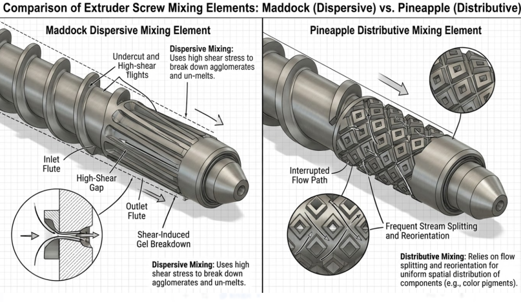
In extrusion, we look at two types of mixing: dispersive and distributive. Dispersive mixing elements (like a Maddock mixer) force the melt through tight clearances under high shear stress. This physically breaks down agglomerates, un-melted resins, and color masterbatches. Distributive mixing elements (like a Pineapple mixer) slice and fold the melt without high shear, evening out the temperature gradients. If you are struggling with color streaks or thermal variations that cause the wire to drift off-center, your mixing geometry is wrong. At BLOOM, we often machine hybrid mixing heads to deliver a melt that is both compositionally mixed and thermally balanced.
Table 3: Comparison of Extruder Screw Mixing Elements for Cable Manufacturing
| Mixing Element Type | Primary Mixing Mechanism | Best Application | Impact on Eccentricity & Quality |
| Maddock (Dispersive) | High shear stress via narrow flutes | Breaking down gels, un-melted particles, and colorants | Prevents hard spots in the melt that physically push the conductor off-center. |
| Pineapple (Distributive) | Flow division and recombination | Evening out temperature gradients in the melt pool | Ensures uniform viscosity, allowing melt to flow evenly around the crosshead. |
| BLOOM Custom Hybrid | Combined shear and flow splitting | Highly demanding compounds like LSZH and XLPE | Delivers optimal thermal balance and pressure stability for tight tolerances. |
Combating Wear to Maintain Long-Term Tolerances
Even the best screw design will fail if it wears down prematurely. The radial clearance between the screw flight and the barrel wall is critical. For a standard 90mm extruder, the factory clearance might be 0.15mm. If abrasive materials (like heavily filled LSZH or semi-con compounds) wear that clearance down to 0.35mm, you will experience severe “leakage flow.”
Leakage flow is when the pressurized melt leaks backward over the flights instead of being pumped forward. This destroys your pressure stability, drastically reduces output, and makes maintaining wall thickness impossible. To prevent this, custom screws must be armored. We utilize bimetallic barrel liners and apply PTA (Plasma Transferred Arc) hard-facing—using cobalt or nickel-based alloys like Colmonoy or Stellite—to the flight lands. Gas nitriding the root of the screw further hardens the surface, ensuring that your customized pumping efficiency lasts for years, not months.
Stop Compensating, Start Fixing
If your operators are spending their shifts chasing the centering bolts and your scrap rates are eating into your margins, it is time to look upstream. You cannot force a bad melt into a good cable. Insulation eccentricity and uneven wall thickness are mechanical problems that require mechanical solutions. By moving away from generic, one-size-fits-all equipment and investing in a custom extruder screw designed for your specific polymers and line speeds, you take control of your process.